This is about using AC or DC external supply for headphone amp. Also, using KiCad to layout gridded prototype boards. This project came to mind because I wanted to use 24vdc wall-warts or the usual AC units.
What of Virtual Ground:
There is a good overview of virtual ground circuits on https://tangentsoft.net/elec/vgrounds.html It links to the Meta42 and other obsolete amps that use the TLE2426 rail splitter for battery supplies. I am not fond of the term "virtual ground" because it implies simulation. Ground is not essential for the rail splitter. It becomes grounded when connected to an audio amplifier. I think virtual ground is the third rail produced by splitting.
The virtually grounded rail splitter is fundamentally flawed because it produces two circuits that are connected in series to the power source. If circuit A needs more power, it can only get it after passing through B ... and vice versa. This means that the circuits must be closely balanced. The TLE2426 improves the balance by slightly bypassing the load with the higher voltage.
Crosstalk Mitigation:
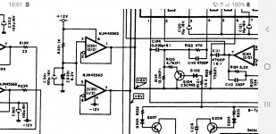
The interaction between splitter nodes results in crosstalk. This can be reduced (I hope) by regulators such as LM317-337. Here is schematic.

I added J2, a half-wave shunt for preliminary test with J3, the 2426 removed. It will work with 9vac to 16vac input. There will be ripple removed by the regulators and input filter caps. The LM317 has a dropout of 1.5v to 2.0v depending upon load. RV1 adjusts the output voltage to the input minus 2v.
I used KiCad to layout the circuit on an ELEG00 PCB which has pretinned vias. These boards are better for soldering then the ones with pads only.


Headphone Buffer:
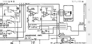
Next up, I produced a different PCB with the headphone buffer. My setup does not need voltage gain, just impedance matching so the buffer is inspired by the NwAvGuy O2.

I am allowing for DC power on a cable between two PCB but these 470uf caps are probably overkill.

What Of The Pretty Box:
I have not assembled a proper case at this time. I just used cardboard.


...
What of Virtual Ground:
There is a good overview of virtual ground circuits on https://tangentsoft.net/elec/vgrounds.html It links to the Meta42 and other obsolete amps that use the TLE2426 rail splitter for battery supplies. I am not fond of the term "virtual ground" because it implies simulation. Ground is not essential for the rail splitter. It becomes grounded when connected to an audio amplifier. I think virtual ground is the third rail produced by splitting.
The virtually grounded rail splitter is fundamentally flawed because it produces two circuits that are connected in series to the power source. If circuit A needs more power, it can only get it after passing through B ... and vice versa. This means that the circuits must be closely balanced. The TLE2426 improves the balance by slightly bypassing the load with the higher voltage.
Crosstalk Mitigation:
The interaction between splitter nodes results in crosstalk. This can be reduced (I hope) by regulators such as LM317-337. Here is schematic.
I added J2, a half-wave shunt for preliminary test with J3, the 2426 removed. It will work with 9vac to 16vac input. There will be ripple removed by the regulators and input filter caps. The LM317 has a dropout of 1.5v to 2.0v depending upon load. RV1 adjusts the output voltage to the input minus 2v.
I used KiCad to layout the circuit on an ELEG00 PCB which has pretinned vias. These boards are better for soldering then the ones with pads only.
Headphone Buffer:
Next up, I produced a different PCB with the headphone buffer. My setup does not need voltage gain, just impedance matching so the buffer is inspired by the NwAvGuy O2.
I am allowing for DC power on a cable between two PCB but these 470uf caps are probably overkill.
What Of The Pretty Box:
I have not assembled a proper case at this time. I just used cardboard.
...

JRC4556 are very good for driving 300 ohm, I used them for composite amp.
However it will add distortion when driving low impedance 32 ohm HP at 0.00X% THD+N, which is still pretty good.
300ohm is about 0.0002%.
However it will add distortion when driving low impedance 32 ohm HP at 0.00X% THD+N, which is still pretty good.
300ohm is about 0.0002%.
I noticed that you don't have the typical ceramic decoupling capacitors near your opamps. Have you looked at the output on a scope to verify it isn't unstable? On a solderless breadboard I have seen njm4556 oscillating without a local cap, but perhaps you are getting away with it on your protoboards since the electrolytics aren't too far from the chips (?).
jason
jason
I only have a BitScope not useful for analog work. And I was mainly interested in power supply flexibility with a low-quality amp circuit as a monitor. Another goal is to learn KiCad so I can produce a proper audio amplifier PCB. I read somewhere that ceramics may oscillate in certain frequency band so I used solid tantulum for regulator stability.I noticed that you don't have the typical ceramic decoupling capacitors near your opamps. Have you looked at the output on a scope,,,
You missed the point of a virtual ground beneffit entirely when using two regulators...You only need one regulator and a low noise dc virtual ground to refference your op-amps ... Download Nakamichi BX300 service manual and get inspired.For my hybrid ic+ germanium headphones amp I used a UA 7810reg and a REF02 (5v ) to split refference the 10 V in half .Thus I don't need to handle two regs noise and their mismatched common mode noise.
Using a 20v reg and a LT ACP 10v ultralow noise refference will allow the use of any amp but a +-5v supply will help a njm4556 op amp like driving low Z loads with less thermal distortions. Even lm4562 can deal with many headphones when supplied very low as it works at +-2.7v vert well.You can check out headphones op amps working with as low as +-1V rails as well.Many usb dac s use them successfully and many of the old forgotten walkmans used older variations of low supply op amps .
You don't need to go extreme lengths as using a ref2 or LT ultra lownoise ref ...but splitting the ground from one regulator has the potential for lower noise no matter the voltage range you choose for supply.
Just a quick tip on using njm4556 as a buffer: you may wanna try a common mode cancelation resistor ranged 1k...100k as in Nakamichi CR4.
You might consider Nak's regulators as well...They were too great at building low noise equipment to ignore their designs.
About smarter uses of njm4556 chips:
https://www.diyaudio.com/community/threads/diy-headphone-amp-recomendation.388265/#post-7073893
Attachments
Last edited:
dreamth: "used a UA 7810reg and a REF02 (5v ) to split refference the 10 V in half .Thus I don't need to handle two regs noise and their mismatched common mode noise."
I do not understand your regulation circuit. Maybe you can point to a simple schematic that demos the concept. I looked at the BX300 schematic which was too dense and monolithic for me.
My supply PCB operates with 24vdc, 16vac full-wave, and 9vac half-wave so both regulators are essential. The LM317-337 are not bothered by virtual ground (VG), which is just an abstraction, because they float. The voltage source for the regulators C1, C2 must be high enough to prevent dropout. Then the regulated voltages are constants so that the common-rail is stable on the output side. GND is system GND.
I spent much time tinkering with KiCad for PCB proto board layout. Noise can be managed by careful filtering. Next version I will pay more attention to that.
The last photo of that post: https://www.diyaudio.com/community/threads/germanium-foundation-chapter1.381869/#post-6961885
You missed the point of a virtual ground beneffit entirely when using two regulators...You only need one regulator and a low noise dc virtual ground to refference your op-amps ... Download Nakamichi BX300 service manual and get inspired.For my hybrid ic+ germanium headphones amp I used a UA 7810reg and a REF02 (5v ) to split refference the 10 V in half .Thus I don't need to handle two regs noise and their mismatched common mode noise.
Using a 20v reg and a LT ACP 10v ultralow noise refference will allow the use of any amp but a +-5v supply will help a njm4556 op amp like driving low Z loads with less thermal distortions. Even lm4562 can deal with many headphones when supplied very low as it works at +-2.7v vert well.You can check out headphones op amps working with as low as +-1V rails as well.Many usb dac s use them successfully and many of the old forgotten walkmans used older variations of low supply op amps .
You don't need to go extreme lengths as using a ref2 or LT ultra lownoise ref ...but splitting the ground from one regulator has the potential for lower noise no matter the voltage range you choose for supply.
Just a quick tip on using njm4556 as a buffer: you may wanna try a common mode cancelation resistor ranged 1k...100k as in Nakamichi CR4.
You might consider Nak's regulators as well...They were too great at building low noise equipment to ignore their designs.
About smarter uses of njm4556 chips:
https://www.diyaudio.com/community/threads/diy-headphone-amp-recomendation.388265/#post-7073893
NwAvGuy material is very good for HP amp design and he uses a single winding transformer to get dual supply.
Single supply hp amp circuit are dinosaurs and rightfully should left it to die.
Single supply HP amp will have issue for it's low frequency, dual supply amp will not such issue.
Really? !NwAvGuy material is very good for HP amp design and he uses a single winding transformer to get dual supply.
Single supply hp amp circuit are dinosaurs and rightfully should left it to die.
Single supply HP amp will have issue for it's low frequency, dual supply amp will not such issue.
https://www.diyaudio.com/community/...-to-the-audiophile-world.348890/#post-6065578
https://www.diyaudio.com/community/...-to-the-audiophile-world.348890/#post-6065905
The single winding (half-wave) wall-wart is good for being simple and economical but it is compromised by being dead half the time. It needs the filter caps to be like batteries. And the input voltage must be extra high to avoid regulator drop-out during the 16 millisecond dead time.NwAvGuy material is very good for HP amp design and he uses a single winding transformer to get dual supply.
Single supply hp amp circuit are dinosaurs and rightfully should left it to die.
Single supply HP amp will have issue for it's low frequency, dual supply amp will not such issue.
But there is a non-functional advantage compared to having a step-down transformer in a DIY project. The wall-wart version can be in a smaller case. Suppose my uncertified DIY project with an integrated transformer sparks a fire .. the insurance company may refuse to cover the cost because the DIY does not have a UL sticker. The wall-wart version can mitigate that risk.
That's why it's useful for headphone amp, the amp's output power is below 10mW.The single winding (half-wave) wall-wart is good for being simple and economical but it is compromised by being dead half the time. It needs the filter caps to be like batteries. And the input voltage must be extra high to avoid regulator drop-out during the 16 millisecond dead time.
But there is a non-functional advantage compared to having a step-down transformer in a DIY project. The wall-wart version can be in a smaller case. Suppose my uncertified DIY project with an integrated transformer sparks a fire .. the insurance company may refuse to cover the cost because the DIY does not have a UL sticker. The wall-wart version can mitigate that risk.
I would prefer to have more capacitance & higher VA transformer than higher voltage.
Single supply (from SMPS) design uses virtual ground may induce noise when connect unbalance signal from PC.
This is about using AC or DC external supply for headphone amp. Also, using KiCad to layout gridded prototype boards. This project came to mind because I wanted to use 24vdc wall-warts or the usual AC.....
Today I stuffed the two PCBs into a Hammond 1591 plastic box seen here with OPPO PM2 and Audio-Technica headphones. These experiments are rough looking but there are good looking projects available within diyAudio which I hope to imitate in future.
Here is another photo taken with the Whammy. The Whammy does battle with my air conditioner so I am saving it for cold winter days.
- Home
- Amplifiers
- Headphone Systems
- Headphone Buffer; AC-DC Supply; KiCad plans prototype PCB