Hi guys,
can anyone tell me in short and simple how to determine the current that is flowing through Q4 and Q5. Also I would like to know if this amplifier would theoretically work - it is similar to Borbely headphone amplifier made with jfet on input (Q6 and Q7 are 2sk389).
I would like to make headphone amplifier from Borbely but doesn't have j511 and also no output mosfet's (2sj79, 2sk216) - so this sch is perfect for me - but I am not sure about the quescient current and also if this would work - to complicated for my puny brain") ).
).
Please help and best regards to all of You
sunny
can anyone tell me in short and simple how to determine the current that is flowing through Q4 and Q5. Also I would like to know if this amplifier would theoretically work - it is similar to Borbely headphone amplifier made with jfet on input (Q6 and Q7 are 2sk389).
I would like to make headphone amplifier from Borbely but doesn't have j511 and also no output mosfet's (2sj79, 2sk216) - so this sch is perfect for me - but I am not sure about the quescient current and also if this would work - to complicated for my puny brain
).Please help and best regards to all of You
sunny
Attachments
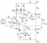
Thanks - that's what I had in mind.... I was not sure about it since mr. Borbely said in his document no. EB-804-421 and EB602-210 that he uses 100-160ma.... and from this calculation we get arround 8mA. That is strange...... I would like to construct Borbely headphone amplifier but with 160mA quescient current and IRF610/9610 combination - current like in EB602-210 document.
How do You calculate the current in this - original sch that is attached here.... it confuses me... those 2sk216 need smaller Vgs to start conducting - right?
p.s. (schematic for p.s. is in the post after this one - it is the original sch from the EB602-210) it is a bit confusing - since in his original document (EB-602-210) mr. Borbely sais that 6.8ohm or 3.9 ohm for the R12 (o.k. he also uses transistor instead of the zener diode)... i can calculate this - bjt needs 0.6V - so Iq=0.6/3.9ohm...... this is o.k. but how to calculate R10
Attachments
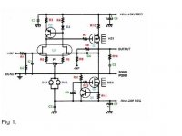
this is the sch i am talking about in p.s. part of my previous mail.....
i would like to substitute j511 with a transistor and Q2 and Q4 with IRF610 and IRF9610 - easier to find but also I would like to have 10-160mA of quiescient current.........
R11 would be 10k and R12 would be 100ohm. I would say that I would like 3.6V on my Q4 gate so that Vgs is 3V (I loose 0.6V on R13). So, Ic for Q5 is Ic=(24-3.6)/10k=arround 2mA. Is this o.k.? What about R10? And how to calculate transistor that would substitute D1a and D1b like in sch in my first mail??
Attachments
I think you can manage your calculations by yourself if you only get datasheets for the transistors. If you know which currents your interested in you will also know the Vgs, if you only have the datasheets.
You could also use the freeware LTSpice and fetch the simulations models in mind. I'm sure Netlist can supply you
If you play around with LTSpice you'll also see the working points without too much work. You will also get distortion, bandwidth and step response in the same time.
You could also use the freeware LTSpice and fetch the simulations models in mind. I'm sure Netlist can supply you
If you play around with LTSpice you'll also see the working points without too much work. You will also get distortion, bandwidth and step response in the same time.
yes - but i didn't simulate anything at all so it would be a little bit difficult to use LT SPice.... I am on it on Yahoo groups but it is progressing slowly..... oh, well ..... i will look at the sch a little bit .... i think that I will calculate something than draw it and post here for someone to say if it is o.k. or not.... we all learn thanks for Your help P-A
Attachments

Nice!sunrise said:No one like my cat picture
Burmese?
Arne K
(Used to have Abbysinian)
How come? Have you tried? It's not particulary hard. If you want to do some FFT and check distortion it may require some help but people here can tell how you should do. It's only a setting. Even I did manage to get nice distorion charts after some help.sunrise said:
Just draw the schematics and get simluation models for those parts that aren't including in the software. Those can be hard to find but also this can be solved.
Cobra - I don't know about the cat - i have been told that it is british shorthair..... oh well - as long as it is nice mijaueeee
Yes, i have tried - but i am stupid or something cause it is going with problems and slow..... it is not a problem to draw an sch in it but to simulate it..... stil having problems to simulate a simple resistor divider so i have thought to made it in the old fashion way - besides i would better (I think) understand the circuit if i would know how to calculate everything... i think.... lthough i would like to simulate it (but after i build it) just to be sure that it would work in strange conditions.... also i would like to try the same in real life.... i like my headphones and wouldn't like to burn them
i am going to draw something like i have promissed and post it a little bit later.....
regards
sunny
this one is for cobra
mijaueeee peranders said:
How come? Have you tried? It's not particulary hard. If you want to do some FFT and check distortion it may require some help but people here can tell how you should do. It's only a setting. Even I did manage to get nice distorion charts after some help.
Just draw the schematics and get simluation models for those parts that aren't including in the software. Those can be hard to find but also this can be solved.
Yes, i have tried - but i am stupid or something cause it is going with problems and slow..... it is not a problem to draw an sch in it but to simulate it..... stil having problems to simulate a simple resistor divider
so i have thought to made it in the old fashion way - besides i would better (I think) understand the circuit if i would know how to calculate everything... i think.... lthough i would like to simulate it (but after i build it) just to be sure that it would work in strange conditions.... also i would like to try the same in real life.... i like my headphones and wouldn't like to burn them i am going to draw something like i have promissed and post it a little bit later.....
regards
sunny
this one is for cobra
Attachments

It's getting cold outside...
- don't you need ear-warmers?
Arne K
sunrise said:.... i like my headphones and wouldn't like to burn them
- don't you need ear-warmers?
Arne K
Re: It's getting cold outside...
IT'S A GOOD ONE I MUST SAY oh, they heat my ears that is for sure......
o.k. - i have tried to calculate something with my limitied knowledge of everything..... i would like to ask someone to check it please...... very big please it is......
i have combined a little bit of few schematics and some current sources that i am not sure how to calculate so i have put what i came up with.....
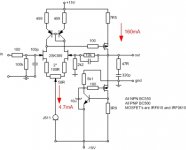
mos current is 160mA and current in front stage is 4.7mA (so that i could substitute j511 with ccs)....
Cobra2 said:
- don't you need ear-warmers?
Arne K
IT'S A GOOD ONE I MUST SAY
oh, they heat my ears that is for sure...... o.k. - i have tried to calculate something with my limitied knowledge of everything..... i would like to ask someone to check it please...... very big please it is......
i have combined a little bit of few schematics and some current sources that i am not sure how to calculate so i have put what i came up with.....
mos current is 160mA and current in front stage is 4.7mA (so that i could substitute j511 with ccs)....
Attachments
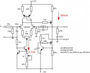 hmm- no suggestions, coments.... no errors..... can not be..... something must be wrong how about those 5k1 resistors that go to the gnd.... or those 499R resistors.... or maybe whole ccs is not right? maybe something could be made better thatn suggested here? is this going to work? oh well - to much q's for one mail....... regards
sunny
oh no - not a simulation again.... i will perform an ritual something on myself really..... i would rather build it first without the cap and then with the cap and ask my friend to test it with function gen and osciloscope..... hope he will say yes....
What do You think - would it be better to use j511 or some bipolar transistor instead of the j511 (somehow connected - maybe like in post 14)?.....
i would rather build it first without the cap and then with the cap and ask my friend to test it with function gen and osciloscope..... hope he will say yes....What do You think - would it be better to use j511 or some bipolar transistor instead of the j511 (somehow connected - maybe like in post 14)?.....
- Status
- This old topic is closed. If you want to reopen this topic, contact a moderator using the "Report Post" button.
- Home
- Amplifiers
- Headphone Systems
- headphone amp similar to Borbely jfet design