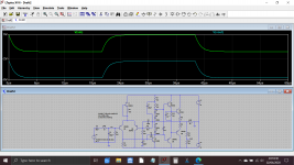
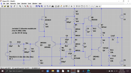
So quite a lot of changes here, in particular using a JFET as a current source and tweaking the compensation cap values.
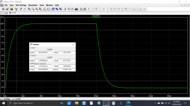
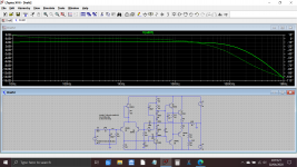
Also added an input filter to deliberately limit the rate of change of any applied input signal. It looks drastic but in reality its pretty good as can be seen by the frequency response.
The first image shows the poor slew rate on the positive going side but OK on the negative. The input filter overcomes this or at least allows the amp to handle whatever we throw at it.
The output is monitored via a divider to equalise the apparent levels.
Also added a bootstrap to the driver stage.
Attachments
Thanks for doing that!
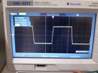
I'm not getting that ringing that you're getting on the simulation at 25kHz. Here is the scope trace from the actual amplifier at 25kHz with a 30 ohm load.

To me, on your improved version, it looks like the slew rate is about 3.5 V/uS. Is that right?
My quick calculation gave a minimum required slew rate of 0.142 V/uS. That's assuming a 32ohm load and an audio output of 40mW RMS. Does that seem right or am I missing something?
Thanks for your help!
James
I'm not getting that ringing that you're getting on the simulation at 25kHz. Here is the scope trace from the actual amplifier at 25kHz with a 30 ohm load.
To me, on your improved version, it looks like the slew rate is about 3.5 V/uS. Is that right?
My quick calculation gave a minimum required slew rate of 0.142 V/uS. That's assuming a 32ohm load and an audio output of 40mW RMS. Does that seem right or am I missing something?
Thanks for your help!
James
Attachments
Very close 🙂
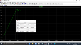
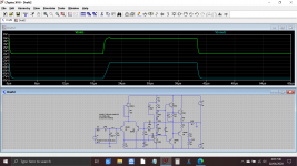
Over a 10 volt output signal range the slew rate is around 3.75 per microsecond as measured between 1 and 9 volts in the output waveform.
If we remove the input filter the raw slew rate of the amp is around 7.5 volts per microsecond (scale expanded here and measured directly over 1us interval.
The input filter takes the amp out of any possible slew rate limiting although to be fair nothing in audio would approach that limit here.