I want a nice amp for my desk. Sure I could buy a kit somewhere, but that is not my style. It certainly wont help me learn very much.
This is what I have been working on for now. A basic concept with expensive components. I call it the kitchen sink.
Tell me what you think. Am I nuts?
This is what I have been working on for now. A basic concept with expensive components. I call it the kitchen sink.
Tell me what you think. Am I nuts?
Attachments
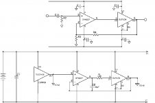
So, it's a PIMETA but without the Jung Multiloop topology?
It's a perfectly sound concept - I have a PIMETA here using OPA827 in a browndog adaptor for L/R and OPA227 in the ground, all buffered with BUF634.
In short: It'll work really nicely if you can make a good board layout for it. The benefits of Jung Multiloop are pretty small, anyhows, but I'd go and analyse Tangent's schematic for the PIMETA, to see if you can understand the close relationship between that design and this one.
If you're not fussed about producing your own board, I'd do the aforementioned analysis of the PIMETA circuit, recognise that it's essentially the same and that you've gained what understanding is to be had, and buy the PIMETA board, as its layout is both excellent and compact.
If, however, you want to produce your own PCB, go ahead, knowing that this schematic is sound (although I'd like to know what sizes you had in mind for the caps on the opamp and buffer rails. Checking the PIMETA and Mini3 designs should help you determine those).
I tried to look at it but for some reason his site is throwing up an internal error message on the PDF's. At least it was last night.
Since size wont be a concern I might just build it on perf board. Mouser is the only place that has the 827 in stock right now and I can't really determine the package available. The 827 looks rather impressive on paper. Judging from the demand I would say that they sound quite nice.
Since size wont be a concern I might just build it on perf board. Mouser is the only place that has the 827 in stock right now and I can't really determine the package available. The 827 looks rather impressive on paper. Judging from the demand I would say that they sound quite nice.
LOL, the PIMETA is the same thing(no doubt way better). Looks like I'm in for one of those then. The parts selection guide pretty much explains the whole thing. I did learn a lot from making that schematic. It adds context to the concepts I have been reading about.
PIMETA here I come.
@TheSeekerr
Did you find that the 227 in the ground channel was better than an 827 or was your decision based upon the 227 being DIP8?
PIMETA here I come.
@TheSeekerr
Did you find that the 227 in the ground channel was better than an 827 or was your decision based upon the 227 being DIP8?
Um.....sort of the second. I forgot to buy an adaptor for single SO-8 to to DIP-8, and at the time, the browndog adaptor being my first experience with surface mount soldering, I wasn't feeling brave enough to solder the OPA827 to the pads on the bottom of the board. I might do that later, just for the sake of completeness.
(Yes, if you have a close look at the layout, there are pads for SO-8 on all the chips - obviously this doesn't help with using OPA827 in OP-L/R, since you'll still need an adaptor to convert from singles to dual, and the DIP-8 version of that adaptor is tidier. Keep in mind that there isn't, and will probably never be, a DIP-8 version of OPA827.)
(Yes, if you have a close look at the layout, there are pads for SO-8 on all the chips - obviously this doesn't help with using OPA827 in OP-L/R, since you'll still need an adaptor to convert from singles to dual, and the DIP-8 version of that adaptor is tidier. Keep in mind that there isn't, and will probably never be, a DIP-8 version of OPA827.)
OK, I just swapped in the OPA827 - killed one, I soldered it in the wrong way around, but fortunately I noticed the 3V offset on the ground channel before it killed anything else.
The only tangible benefit is improved hum rejection....before it was quite sensitive to the placement of the input and output wires, whereas now it seems happier.
As to the demand - the specifications are on par, and in some cases better, than the OPA627. I'm pretty sure everyone just wants to know if 827 is really the equal of 627 at a quarter of the price.
That makes sense. I have never tried to solder any surface mount. I have been soldering through the hole for years. I find that the grip on the iron is too far away from the tip and I don't have as much control as I would like. I have yet to find one where the grip wasn't a mile away. It's kinda like shooting pool one handed. I think that before I attempt anything small I'm going to invest in some solder paste and make myself a hot air re flow gun like this.
http://www.engadget.com/2006/03/07/how-to-make-a-surface-mount-soldering-iron/
http://www.engadget.com/2006/03/07/how-to-make-a-surface-mount-soldering-iron/
I've actually found it really easy to solder SO-8's by using the "flood and suck" method.
Basically, you tin one pad, slide the chip on, and melt the solder to tack that leg in place. Then, with none too much care, solder in the legs on the opposite side, then clean up any bridges with some solder wick, but just quickly and lightly, so the solder underneath the legs remains to make the joint. Repeat for the other side, check for bridges, and you're done. It's actually really fast, and you get the hang of it after the first chip or two.
Basically, you tin one pad, slide the chip on, and melt the solder to tack that leg in place. Then, with none too much care, solder in the legs on the opposite side, then clean up any bridges with some solder wick, but just quickly and lightly, so the solder underneath the legs remains to make the joint. Repeat for the other side, check for bridges, and you're done. It's actually really fast, and you get the hang of it after the first chip or two.
- Status
- Not open for further replies.
- Home
- Amplifiers
- Chip Amps
- headamp design check.