Hello,
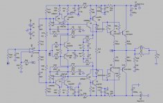
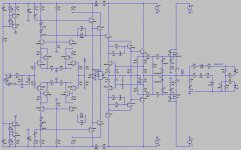
This is high feedback conceptual amp, incorporating two of Hawksford ideas - the EC circuit and the balanced EF for the VAS.
Feedback at 20kHz is 66dB, margin is 60 deg.
The LT1115 opamp was used only due to it's specs (FET input, 40MHZ BW). No other reason.
Circuit:
This is high feedback conceptual amp, incorporating two of Hawksford ideas - the EC circuit and the balanced EF for the VAS.
Feedback at 20kHz is 66dB, margin is 60 deg.
The LT1115 opamp was used only due to it's specs (FET input, 40MHZ BW). No other reason.
Circuit:
Attachments
Hi, Jorge,
I dont understand the mathematics of Hawksford EC.
But in your schematic, why dont you just connect output of opamp to the emitors junction of MPSA06/56 (Q12)? I think this way it will provide error correction too, with simpler cct.
And change the above/below transistors (Q7,8,11,14) to CCS.
I dont understand the mathematics of Hawksford EC.
But in your schematic, why dont you just connect output of opamp to the emitors junction of MPSA06/56 (Q12)? I think this way it will provide error correction too, with simpler cct.
And change the above/below transistors (Q7,8,11,14) to CCS.
Hi
I suspect your PSRR results are so good mainly because very high feedback of an op-amp. The fact is such topology is asking for separate regulated power supply for everything but output stage. Voltage dividers from rail voltage and local feedbacks from collector to base of a darlington just won't play good. Keep in mind that simulated caps (like C3 and C13 or C14/16) have zero ESR and ESL, which won't be that nice in reality.
I also think you don't need C7/9, CFPs won't like capcitive loads, better to manipulate with R21/27/30/31/23 and get rid of these caps.
Hawksford EC is just fine, guess R22 should be a pot to adjust bias.
The thing, that makes me wonder are your 'YZ' connections. Probably you intended smart and efficient driving of VAS transistors. But what happens at high frequency, when input capacitances become significant, collector currents of Q8/11 are 90deg. phase shifted with voltage and so on..??? What is your reasonig here?
best regards
Hello, lumanauw
I will look at your suggestions.
Hello, darkfenriz
Yes, PSR is heavily NFB based, but caps have series resistences - 0.028 for the 3300u, 0.041 for the 1000u and 0.07 for the 470u (LTSpice doesn't shows it in the scheamtic).
C7/C9 balances the Hawksford loop.
Look at the compnsation loop of the VAS - C5, R28, R35 (C6, R29, R36). This network defines the VAS output impedance, and it's not constant through the audio band.
To balance the EC, one needs a similar impedance feeding the EC transistors.
And R30/R31 are high enough in value to keep the CFP stable.
The Y/Z connections are suggested by Hawksford in the Super Cascode paper.
He states it's a minor enhancement, but I thought it would be worth the cost... 🙂
Jorge,
Congratulations. You're fast! Within a day after finishing the Hawksford output in the other thread you already have the amp completed. Now the practical part...
The Hawksford balanced EF is nice too; I had forgotten that one.
Steven
Congratulations. You're fast! Within a day after finishing the Hawksford output in the other thread you already have the amp completed. Now the practical part...
The Hawksford balanced EF is nice too; I had forgotten that one.
Steven
Hi,
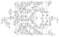
I have been busy too...Just a mixbag sch from Pavel Dudek, Steven, Cordell, Mark, Borbely...(you name it). And it works (sort off), to my surprice...Not bad for a newbee
One Q: How to lose a global NFB loop and in the same time keep the same gain and cascode over input diff. pairs?
I have been busy too...Just a mixbag sch from Pavel Dudek, Steven, Cordell, Mark, Borbely...(you name it). And it works (sort off), to my surprice...Not bad for a newbee
One Q: How to lose a global NFB loop and in the same time keep the same gain and cascode over input diff. pairs?
Attachments
Hi aparatusonitus
honestly I don't dee how bias is adjusted here, also unlike Dudek's one I don't see how the correction 'corrects' in your amp. Could you give some details about how it is to work?
regards
honestly I don't dee how bias is adjusted here, also unlike Dudek's one I don't see how the correction 'corrects' in your amp. Could you give some details about how it is to work?
regards
Hi darkfenriz,
I have adjusted current (~300mA) over output mosfet pair is by resistors R54 (61R), R61(1k82) and R7 (82R) + P1. EC circuit if there is one as you notice, does not correct anything yet . Any hint?
I have adjusted current (~300mA) over output mosfet pair is by resistors R54 (61R), R61(1k82) and R7 (82R) + P1. EC circuit if there is one as you notice, does not correct anything yet
. Any hint?Steven
The basic amp topology was already simulated - it was when I had problems with the Hawksford EC that I started the other thread....
It will take some time for a practical amp - PCB layout is not my forte (read I dislike doing it)!
darkfenriz
Not many (any?) high OL gain amp will have a low PSR open loop.
To obtain high gain the VAS load has to be quite high - say over 100K ohms; this way, even using a cascode there's almost no PSR!
aparatusonitus
The EC circuit connection in your circuit is wrong - the collectors of the EC transistors are connected directly to the emitters of the BF471 (?) when they should be to the base of the following transistor BCXXX (sorry, hard to see the numbers...)
Check that.
The EC circuit connection in your circuit is wrong - the collectors of the EC transistors are connected directly to the emitters of the BF471 (?) when they should be to the base of the following transistor BCXXX (sorry, hard to see the numbers...)
Check that.
aparatusonitus
Jorge is probably right (I also cannot see the numers).
Look how Pavel does it :
http://www.diyaudio.com/forums/attachment.php?s=&postid=605255&stamp=1111726639
Jorge
sorry, but I have problems understanding what you mean.
PSR- power supply ripple
PSRR- power supply ripple rejection, right?
How VAS load affects PSRR? I do not understand.
regards
Jorge is probably right (I also cannot see the numers).
Look how Pavel does it :
http://www.diyaudio.com/forums/attachment.php?s=&postid=605255&stamp=1111726639
Jorge
Not many (any?) high OL gain amp will have a low PSR open loop. To obtain high gain the VAS load has to be quite high - say over 100K ohms; this way, even using a cascode there's almost no PSR!
sorry, but I have problems understanding what you mean.
PSR- power supply ripple
PSRR- power supply ripple rejection, right?
How VAS load affects PSRR? I do not understand.
regards
darkfenriz said:Jorge
sorry, but I have problems understanding what you mean.
PSR- power supply ripple
PSRR- power supply ripple rejection, right?
How VAS load affects PSRR? I do not understand.
regards
PSRR - Power Supply Rejection Ratio; I used PSR as Power Supply Rejection.
The noise (ripple + whatever) is in the supply line; the VAS stage is between the supply line and its collector load - speaker impedance multiplied by the gain of the EFs between speaker and VAS in a first cut.
For one transistor - 8*30; for 2 (Darlington/CFP) - 8*30*30; for 3 EFs 8*30*30*30.
So the VAS collector load may go from a minimum of some 2400 to a maximum of over 216K ohms.
As the load impedance rises, the lesser the VAS can attenuate any noise in the suplly line (look to it as a voltage divider - VAS/collector load).
- Status
- Not open for further replies.
- Home
- Amplifiers
- Solid State
- Hawksford based conceptual amplifier