Thanks for your reply. It was normally lighting the -20dB led. For sure the Fluke leads had an issue. I replaced and now get reliable readings, seemingly in the right range. post# 40 gives my updatesThat Crown will deliver its rated power. Were you lighting up the -20dB or -10dB indicators?
Thanks for your replies. I was able to isolate my measurement mistake to a somehow faulty test lead. My updated measurements are now in post #40. Your intuition was quite right.How did you measure the 2,4V AC? I hope not by a multi-meter. Anyway, that doesn't really matter. In a ripole it's absolutely impossible to get 104dB/1W/1m, even with dual 15". realistically, you're at 90, at most 93dB. Your drivers are 4 Ohm, so with two of them you're already at already 8W! That means you already reach the max power below your target 105dB @ 3m. And there's still no headroom in it!
The vents are designed to get rid of heat (energy exposure?), and chuffing is not a concern from a longevity standpoint.Based on the air chuffing, I'm hesitant to push further at that frequency, also because of the energy exposure. I'd rather not speculate on their actual excursion, but it's further than I'd ever push them, just aerodynamically. I'll be applying a HPF at 25Hz in the end.
Doubling excursion gives you +6dB more output, without checking, you have no idea of potential headroom, or what voltage is needed.
I'm still curious as to the excursion, you could check at any visible excursion you are comfortable with and just reference the voltage.
Art
The vents are designed to get rid of heat (energy exposure?), and chuffing is not a concern from a longevity standpoint.
Doubling excursion gives you +6dB more output, without checking, you have no idea of potential headroom, or what voltage is needed.
Not only that, but it also reduces the power compression by cooling and reducing the excursion (like you already mentioned). That might add additional +1 or maybe even +2dB long term output if driven hard.
I'm still curious as to the excursion, you could check at any visible excursion you are comfortable with and just reference the voltage.
Visible check on the excursion is very unreliable. It's a hint and can be used by experienced techs like you but is genrally just a very coarse indicator.
Anyway, a low-cut and rised lower frequency requirement will easily push the max spl by 10dB. If you don't want that and aren't satisfied with the spl then the only solution is to put more subs in place.
Agreed. in total, 4x 15" drivers will simply have to be enough for me, (WAF and all) and I'll manage the headroom as you suggested.Anyway, a low-cut and rised lower frequency requirement will easily push the max spl by 10dB. If you don't want that and aren't satisfied with the spl then the only solution is to put more subs in place.
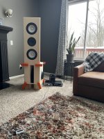
I Do 🙂.Got any pics of your setup?
The Ripole enclosure and front plate baffle are both made of baltic birch, and both experimental at this stage. I've been working out multiple variables along the way, but I've basically settled on this arrangement over the course of a few months.
The front baffle is currently held in place using parallel clamps. This baffle was from an earlier experiment where the ripole was much smaller, which is why it doesn't fit exactly. I still plan to optimize the baffle dimensions, shaping (front radius curve carved on CNC), and driver spacing, although currently I've extremely happy with the horizontal and vertical responses thus far. Basically, I can freely sit, stand and walk around the room without noticing a change in the tone. Measurements basically confirm this off-axis behavior up to 60deg, although I've not been so precise in my angles and distances. Just looking at smoothness off axis is giving me enough confidence to not dig deeper.
Finally, The ripole polar pattern that I notice in room needs some further optimization. I'm deciding whether or not to rent a large anechoic space for a day, or use the somewhat smaller one at my company to investigate this, or simply to wait until spring/summer to test outdoor. its certainly directional, but not optimum for my room arrangement yet. i can tune this, but need to test further to verify.
The enclosure width right now is 14". The front slot opening is 22.5" x 3.125" (give or take).
Attachments

Enclosing the magnets in the rear facing slots would go a long way in reducing the vent noise.Finally, The ripole polar pattern that I notice in room needs some further optimization. I'm deciding whether or not to rent a large anechoic space for a day, or use the somewhat smaller one at my company to investigate this, or simply to wait until spring/summer to test outdoor.
For a room to be anechoic down to 25Hz the absorption material depth would have to be near 1/4 wavelength ~11.3 feet (3.5meters) on all sides. The room would be huge.
There are few anechoic rooms with more than one meter of absorption material, which is good to ~100Hz, above the typical "subwoofer" range.
Your corner placement will make the rear reflection's phase alignment more "interesting" than the typical null parallel to wall arrangement.
You may find MalVeauX's similar ripole ("W" frame slot) outdoor tests interesting:
Update, new prototype finished. Measured.
21" wide, 13.5" tall, 13.5" deep. Internally about 1.6 ft^3 displaced. W-frame slot loaded open baffle
GRS12SW-4 x 2 ($31 each) wired in series (7.7 ohm)
DATS to see Fb and baffle resonance, noted the 225~240hz spike expected from the slot cavity resonance.

The crude form:


Measurements:
Ground plane 1 meter
First, I took my jig out and took them to peak to peak xmax over 16mm, and they were still...
21" wide, 13.5" tall, 13.5" deep. Internally about 1.6 ft^3 displaced. W-frame slot loaded open baffle
GRS12SW-4 x 2 ($31 each) wired in series (7.7 ohm)
DATS to see Fb and baffle resonance, noted the 225~240hz spike expected from the slot cavity resonance.
The crude form:
Measurements:
Ground plane 1 meter
First, I took my jig out and took them to peak to peak xmax over 16mm, and they were still...
How do you propose to "tune" a ripole/dipole figure of 8 polar pattern?its certainly directional, but not optimum for my room arrangement yet. i can tune this, but need to test further to verify.
Art
I thought about that too, however, even when I'm up close, it's quite difficult to hear the turbulent noise from the mag vents. The noise that distracts is the literal air trying to escape and enter the main cavity. (chuffing? what's the best "buzz" word for this?) I've had success in the past with large chamfers on the mouth on my ripoles, as opposed to the sharp corners currently in place.Enclosing the magnets in the rear facing slots would go a long way in reducing the vent noise.
Completely agree. I have access to 15m chamber in Canton, MI. I'm mostly loving the idea of a quiet space (to easily measure the null level), and a large space allows me to gate appropriately. But yes, totally agree it's not going to be actually anechoic below 80Hz ( I think that's what that chamber is spec'd to).For a room to be anechoic down to 25Hz the absorption material depth would have to be near 1/4 wavelength ~11.3 feet (3.5meters) on all sides. The room would be huge.
There are few anechoic rooms with more than one meter of absorption material, which is good to ~100Hz, above the typical "subwoofer" range.
Thank you for the link. I'm excited to examine. I've actually built a 4x 10 cone-to-mag arrangement a few times with those GRS drivers. Worked well enough IIRC, but I don't think I still have access to my acoustic measurements from that (maybe 12 years ago now)You may find MalVeauX's similar ripole ("W" frame slot) outdoor tests interesting:
Update, new prototype finished. Measured.
21" wide, 13.5" tall, 13.5" deep. Internally about 1.6 ft^3 displaced. W-frame slot loaded open baffle
GRS12SW-4 x 2 ($31 each) wired in series (7.7 ohm)
DATS to see Fb and baffle resonance, noted the 225~240hz spike expected from the slot cavity resonance.
The crude form:
Measurements:
Ground plane 1 meter
First, I took my jig out and took them to peak to peak xmax over 16mm, and they were still...
My proposal to "tune" directivity is to alter the ratio of open area of the front mouth / rear mouth. I've noticed a change pretty obviously in my room just by restricting airflow on the front mouth, which shifted the first order null angle by about 20 deg. As I walked around the enclosure, it appeard to produce nulls at roughly +/-70-75deg relative to my design axis (0deg), instead of the +/-90 previously. This may have been just a room-mixing of the front and rear radiation strength resulting in room nulls at new locations, not sure. Testing / measurements to follow when I have the time to dedicate to it.
Last edited:
I disagree, persistence of vision and a ruler makes it very easy to measure high excursion subwoofers.Visible check on the excursion is very unreliable.
Since you are measuring peak to peak, any error is divided by two.
Wear hearing protection, and keep the tests short to avoid power compression (voice coil heating increasing impedance) affecting the measurement.
It takes very little experience to read a ruler and a voltmeter (if the leads are working 😉 ).It's a hint and can be used by experienced techs like you but is genrally just a very coarse indicator.
I've found my measurements to reflect HornResp simulations within a millimeter up to near Xmax.
As Xmax is approached or exceeded, simulations become inaccurate since they assume linear magnetic force and suspension compliance, while the visual measurements accuracy increases the higher the excursion.
Art
As you can see in MalVeauX's measurements, the front to back SPL difference below 100Hz is only ~1dB, though back/front mouth area ratio is ~2.75/1.My proposal to "tune" directivity is to alter the ratio of open area of the front mouth / rear mouth. I've noticed a change pretty obviously in my room just by restricting airflow on the front mouth, which shifted the first order null angle by about 20 deg.
Notice MalVeauX's front/back response changed by as much as 3dB above 100Hz.As I walked around the enclosure, it appeard to produce nulls at roughly +/-70-75deg relative to my design axis (0deg), instead of the +/-90 previously. This may have been just a room-mixing of the front and rear radiation strength resulting in room nulls at new locations, not sure.
The constructive/destructive phase relationship of the rear reflected waves to the forward radiation becomes more extreme at higher frequencies, as well as your hearing becoming more sensitive to those changes.
I'd speculate the 20-25 degree shift you heard in the upper range won't apply in the low end.
Good to hear that the pole vents are quiet, they can be quite noisy on some subs.I thought about that too, however, even when I'm up close, it's quite difficult to hear the turbulent noise from the mag vents. The noise that distracts is the literal air trying to escape and enter the main cavity. (chuffing? what's the best "buzz" word for this?)
"Chuffing" is as good a word as any for high particle velocity wind noise.
As you get up close to the near field of the sub, the chuffing is relatively louder compared to the low frequency output.
Your rear vents appear to be around double the area of the front, how does the chuffing SPL compare front to rear?
Virtually nonexistent chuffing at the rearYour rear vents appear to be around double the area of the front, how does the chuffing SPL compare front to rear?
You can't measure p-p because your ruler has to poke into the cone if it is going into positive (outward) excursion if you really want to measure the negative excursion too. Seems it's not me who needs to learn how a ruler works. Where do you place your ruler then? Please don't tell me at the edge of the basket! That only measures how much the surround moves, depending on the driver, that can be a lot less.
Nice story though.
Nice story though.
The method linked in post 3 is simple and effective for measuring p-p excursion.
It confirms that it is not precise, just as I said. Thank you for acknowledging that.The method linked in post 3 is simple and effective for measuring p-p excursion
I hold the paper ruler made from card stock of an appropriate size above the deepest part of the cone and look at the movement of the outer perimeter of the cone near the cone/surround joint. I usually put a tiny white or silver dot on a black cone for better contrast.You can't measure p-p because your ruler has to poke into the cone if it is going into positive (outward) excursion if you really want to measure the negative excursion too. Seems it's not me who needs to learn how a ruler works. Where do you place your ruler then?
Linqwitz "wedge micrometer" measurement tapes the "ruler" to the dust cap:
As he says: "While this is not a precise measurement instrument it is still very useful in relating acoustic distortion data to cone displacement."
In the engineering world, "precise measurements" would be tiny fractions of a millimeter, which would be required if measuring tweeter excursion, but are not at all required for measuring high excursion woofers.
Anyway, if you don't want to DIY, you are welcome to leave measurements to those that find them useful.
Art
Last edited:
Great- just turn the ripole around, flip the top over and re-clamp!Virtually nonexistent chuffing at the rear
Might want to put a grill over it if you don't like the "spokey" look😎
- Home
- Loudspeakers
- Subwoofers
- Having big trouble with my dual 15" Ripole design