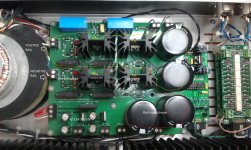
I have just purchased a Blue Hawaii headphone amplifier (HeadWize - Project: Blue Hawaii Hybrid Electrostatic Amplifier for Stax Omega II Headphones by Kevin Gilmore) I'm a novice with electronics, having built a few solid state amplifiers. What I am finding is that I have a power supply MOSFET that is currently running ~20c higher than the other. I disconnected each channel of the amplifier and noticed that the MOSFET still ran considerably hotter, so I do not think it is an amp channel drawing far more current. That leaves bad component(s) in the supply I think. Any ideas on where I should start? This is the supply schematic: http://gilmore2.chem.northwestern.edu/images5/gilmore4_2.png This is a picture of what the amplifier looks like: http://gilmore2.chem.northwestern.edu/images5/gilmore4_4.jpg
Thanks!
Thanks!
Hi, the mosfet power supply looks simple enough...Try measuring voltage
across the 3 zener diodes they should be the same for the good channel.
You could swap the mosfets or replace with another if you've got a spare.
across the 3 zener diodes they should be the same for the good channel.
You could swap the mosfets or replace with another if you've got a spare.
He's gotten this answer elsewhere, but when it came out that he used to go by the handle "trevornetwork", selling other gilmore amplifier designs that were poorly built and dangerous, he was banned.
Ok 'Grawk'. I am not sure what your issue is, but just because I made a poorly built amplifier -SIX- years ago and was banned on A DIFFERENT FORUM does not mean that I cannot solicit the opinion of a more competent forum regarding an amplifier that is obviously not performing as it should. Putting it simply, kindly go away unless you have something useful to contribute.
 Gentlemen, keep to the topic. Personal attacks are against forum rules.
Ok. I've performed the measurements.
For the hot MOSFET. The series zeners measure at: 154V, 153.6V, 50.1V. For the other MOSFET the measurements are: 156.9, 158.1, 52.3.
For the hot MOSFET. The series zeners measure at: 154V, 153.6V, 50.1V. For the other MOSFET the measurements are: 156.9, 158.1, 52.3.
Do you mean one channel is hotter than the other (same device), or one heat sink is hotter than the other heat sink on that same channel?
One MOSFET's heatsink on what I think is the negative rail is 20c+ hotter than the one on the positive rail. The reason why I disconnected each amp board was to check if one of the amp boards was causing additional load on the power MOSFETs. Since that did not seem to be the case as the same MOSFET heated up whether the left or right amp board was connected I suspected a component(s) on the supply board.
I hope I am answering this question correctly. Please let me know if I can clarify.
I hope I am answering this question correctly. Please let me know if I can clarify.
why is it hard to believe that one rail would have a larger current draw than another? Do you understand what grounded grid means?
I'd focus in understanding how basic circuit elements work, like resistors and diodes and then coming back to this "perceived problem" when you have gained a bit more understanding. It seems that you are not even sure which components form the "positive rail" and which are the "negative rail". Also, identify which componets are BJTs. Figure this out first and we can go from there.
I'd focus in understanding how basic circuit elements work, like resistors and diodes and then coming back to this "perceived problem" when you have gained a bit more understanding. It seems that you are not even sure which components form the "positive rail" and which are the "negative rail". Also, identify which componets are BJTs. Figure this out first and we can go from there.
Ok. Well, I'm not sure that commenting that I should go become an EE is a useful comment. If I was an expert on tube amplifier topologies I would have probably not asked the question. With that out of the way, why would a grounded grid topology be likely to cause a higher current draw on one of the rails?
Any other ideas on this one?
Any other ideas on this one?
Please post a picture and label the four device with heat sinks, their temperatures, heat sink height, and what type of device they are. Then circle the devices together that are on the same rail and label both as either positive or negative.
Excellent. So, next what determines power dissipated through that device? For each factor, state whether or not it's a function of something on the PSU board or something on the amp board.
How long was the amp on when you took these measurements, and was there a load attached? Try keeping it on for at least half hour with a load and a signal and compare the results.
How long was the amp on when you took these measurements, and was there a load attached? Try keeping it on for at least half hour with a load and a signal and compare the results.
- Status
- Not open for further replies.
- Home
- Amplifiers
- Tubes / Valves
- Having an issue with a MOSFET in my Blue Hawaii