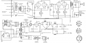
I've been bread boarding this power supply over and over for a month switching things up and I've settled on the design shown here. I used the Quasimodo method to determine the snubber for this Antek transformer.
Would any members have a kind second to desk check it a little?
I do have one specific question though and that is that I chose to establish the virtual ground for the AC filaments using the safety ground, not the audio ground established at Star B or the "dirty" peak voltage raising cap ground established at Star A. Is this ok to reference the filaments to the chassis instead of the audio ground (which is floating from the chassis)? I figured as the filament wires snake around and hug the chassis it was better to have those referenced the same and not get them involved with the establishment of the clean audio ground.
Newbie here.
Attachments
Some of your grounding and power supply choices strike me as unusual and straying from what's known-working and proven.
You've got input and output transformers. Why leave the circuitry floating then? It seems like an invitation for capacitively coupled hum. I would suggest referencing Star B to PE while separating primary and secondary grounds. This would also resolve your concerns re: heater supply.
You are relying entirely on the 220 µF capacitors' health to separate the first and second stages. One of them failing could result in bad oscillation / motorboating. I'd contemplate another RC for the first stage and/or rethinking the whole arrangement entirely.
Which is supposed to be, the advantage on "double rectification"? (SS and tube?) Having two secondaries, wire them in series and us two diode tubes in the classic full wave rectification, eliminating the SS quad diode.
Which is supposed to be, the advantage on "double rectification"? (SS and tube?) Having two secondaries, wire them in series and us two diode tubes in the classic full wave rectification, eliminating the SS quad diode.
My thought is that the rectifier tube is basically acting like a 25 ohm resistor after 12 seconds of slow warm up. And essentially creating another RC stage. It's going to be enclosed in the wooden box, so two tubes is twice the heat to fan out, I wanted slow B+ using a tube rather than a thermistor or some gimmicky solid state timer or an expensive relay tube. I do see your point on going to a full wave rather than a bridge. And on the other poster about eliminating the dedicated filament X former and series stringing that on the main X former. As for SS and tube, I know this is really a SS rectifier with a tube that is not at all needing to be a rectifier, just a governor that settles into being a resistor. This is by design, many have used damper tubes just for slow start B+.
Thanks for looking it over I will investigate moving away from using a bridge.
Some of your grounding and power supply choices strike me as unusual and straying from what's known-working and proven.
You've got input and output transformers. Why leave the circuitry floating then? It seems like an invitation for capacitively coupled hum. I would suggest referencing Star B to PE while separating primary and secondary grounds. This would also resolve your concerns re: heater supply.
You are relying entirely on the 220 µF capacitors' health to separate the first and second stages. One of them failing could result in bad oscillation / motorboating. I'd contemplate another RC for the first stage and/or rethinking the whole arrangement entirely.
Thanks, you've convinced me. I had another RC stage but removed it since I was measuring only 4mv of ripple, under .005% for no load and around .01% while drawing 50ma load. I Thought I was following the tried and true of having the diode negative go to directly to the first filter cap, then star everything else tightly at star B with one connection from first filter neg to star B. I'm a newbie so I assume "PE" means the power entry ground? So I would connect the power entry star right at the IEC to star B and ground the filaments to PE? I will be series stringing the filaments by like current pairs and rewire the filament transformer secondaries in series.
Using a MRC as first cap gave me a much better ripple reading than an electrolytic and that is a punishing position for a capacitor, The MRC is polypropylene in vegetable oil.
I have a Jensen input transformer due to all the common ground sources, many cables, for my computer desk, I didn't want ground loops with this many common ground sources. I see your point, it's all isolated, so no need to lift star B from the mains ground I'm sure one of my iterations had it connected like that along the way.
Full wave and doubler for fans will not work with grounding shown.
This means I should ground it only on the AC side then? I have not bothered to breadboard the fan circuit at all yet, I just thought I'm going to need a fan as this will be in a wooden box, much like a 1960's table radio maybe with the speakers too.
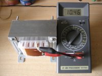
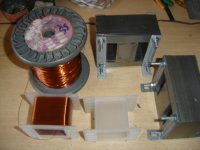
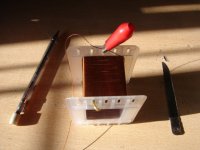
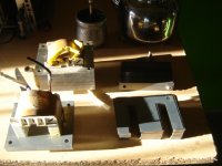
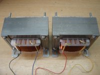
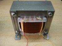
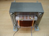
Note that what you did isn't bad. Only, that in my opinion, to waste 10W apx (6.3V @ 1.21.2 Amps) is useless in the way you are doing the circuit. Perhaps an NTC or a switched off relay by passing a resistor can do the job. Or, as I like much more, is to get rid of silicon, and take full advantages of tube rectification: less noise, soft transitions, self soft starting. And those damper diodes perform very well as rectifiers. I use them in my project. 6AX3 but I use choke input filter. Chokes are out of board, obviously.
Attachments
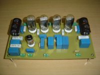

Note that what you did isn't bad. Only, that in my opinion, to waste 10W apx (6.3V @ 1.21.2 Amps) is useless in the way you are doing the circuit. Perhaps an NTC or a switched off relay by passing a resistor can do the job. Or, as I like much more, is to get rid of silicon, and take full advantages of tube rectification: less noise, soft transitions, self soft starting. And those damper diodes perform very well as rectifiers. I use them in my project. 6AX3 but I use choke input filter. Chokes are out of board, obviously.
Wow that's nice work Osvaldo! I was debating this question for a while, to go hybrid or full glass, I settled on this as a compromise. I'm not a fan of relays switching 350+ volts of DC in front of an inductor plus the associated SS timer. NTC I thought of too but that gets very hot and shouldn't be cooled to work, this project is enclosed so I actually want to cool the wooden box interior presenting a dilemma., and NTC fails to slow the B+ if somebody switches the amp off then on again. Relay tubes are an anacronism even for us! So that was my reasoning to go hybrid seeing others do similar.
If you can and want to migrate to full wave tube rectifiers, I can hardly suggest to use choke input, whence you will need a higher transformer voltage, or lower output voltage. Whilst cap input gives output voltage close to 1.4times AC RMS voltage, choke gives you about 0.9.
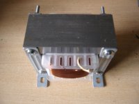
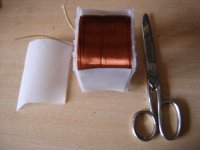
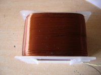
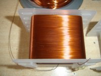
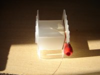
This apparent con or drawback, has several advantages: the transformer "sees" a continuous current demand in place of short high amperage pulses. Second, the rectifiers (Both SS and tube) works in a better manner, also, seing long and flat current pulses in place of short peaks. This makes use of better iron and copper looses and less THD at line currents. VT rectifiers life will be longer too. Also, if the inductor is "large", current spikes while turning on the amp are self limited. See in my project, that I use 680µF 400V rated caps. However, no current peaks at all appears because my own designed chokes are more the 10Hy each one (One per rail).
I suggest to search in the web, a book called "Radiotron" by Langford Smith. It is freely available in pfd format. There are two or three chapters entirely dedicated to power supply design and considerations. Check in one of them for the "hot cathode current peak rating", and you will found that choke filters are self limiting, and then, safer. For you, your tube rectifiers, transformer and neighbors.
Enjoy reading. And learning.
Attachments
-
 Choke 10.JPG149.6 KB · Views: 49
 -
 Choke 09.JPG144.5 KB · Views: 41
 -
 Choke 08.JPG135.3 KB · Views: 42
 -
 Choke 07.JPG159.5 KB · Views: 44
 -
 Choke 06.JPG159.9 KB · Views: 44
 -
 Choke 05.JPG144.1 KB · Views: 47
 -
 Choke 04.JPG153.6 KB · Views: 41
 -
 Choke 03.JPG145.4 KB · Views: 43
 -
 Choke 02.JPG146.4 KB · Views: 45
 -
 Choke 01.JPG149.4 KB · Views: 86
Last edited:
Thanks, well this all still on the breadboard, I may as well try choke input too! I swear I learn more strapping something together on the bench, making 10 mistakes, than a week of reading. Yesterday I watched a metal film resistor go up in smoke, I was one pin off with one of the leads and it was connected directly across the secondary!
- Home
- Amplifiers
- Power Supplies
- Have time to desk check my power supply design?