Midranges spread apart - see arrows. The cluster of 4 or 2 midranges will behave somewhat like a single midrange that has an effective size of roughly the size of the red or violet arrow, respectively.What's wrong with this arrangement?
This is two to three times the diameter of a single midrange by itelf, which means problems with beaming and narrow dispersion will start at one half to one third the frequency of a single midrange driver by itself. You might say this arrangment cripples the midranges, and makes them unable to provide their normal high-frequency performance.
In other words, you'd have to move the crossover frequency down by a factor of about two or three times to avoid worse dispersion than a single midrange would have. Usually this is not possible, because tweeters are not able to work down to such low frequencies.
-Gnobuddy
Attachments
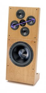
Midranges spread apart [...] This is two to three times the diameter of a single midrange by itelf, which means problems with beaming and narrow dispersion will start at one half to one third the frequency of a single midrange driver by itself.
The DNA might be better than that, if you consider the uneven distances that will exist between the drivers and your ears. This thread covers it well:
A Novel Loudspeaker Array
The DNA might be better than that, if you consider the uneven distances that will exist between the drivers and your ears. This thread covers it well:
A Novel Loudspeaker Array[/QUOTE
Here's the patent.
http://patft.uspto.gov/netacgi/nph-...6,801,631.PN.&OS=PN/6,801,631&RS=PN/6,801,631
DNA Sequence Speakers dipole open baffle woofer high efficiency point source array midrange tweeter treble loudspeaker
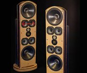
DNA's mid has similar directivity as a 15" driver. The quadruple matches quite well with the dipole 15,5" driver in 18,5" frame. Directivity changes totally when tweeter starts to play! DNA doesn't tell xo points but my quess is 500/3000.
High directivity in midrange is a good thing, but this construction is tricky.
High directivity in midrange is a good thing, but this construction is tricky.
the DNA design (tilted quartet/square) seem to address comb filtering by way of averaging distance traveled - and does not address beaming or polar response.
however lowpassing some of the mids in the array has the potential of addressing both issues - comb filtering and polar response.
lowpassing can simply be done by a coil - but i was wondering whether inverting some of the mids would have a similar effect.
however lowpassing some of the mids in the array has the potential of addressing both issues - comb filtering and polar response.
lowpassing can simply be done by a coil - but i was wondering whether inverting some of the mids would have a similar effect.
Attachments
Last edited:
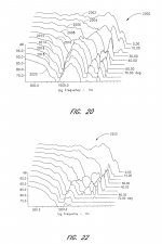
Thanks. The difference between the 'typical' 2x2 array and the patent's skewed array (fig20 vs fig22) is pretty striking - but the skewing doesn't do what I thought it would (based on Patrick's ideas in the other thread I linked).Here's the patent.
The main effect appears to be that it reduces the side lobes by ~15dB.
The patent and measurements in it are just rubbish. The 4-driver flower is acoustically like a single 15" driver. They are just comparing it's directivity to a single 5" driver or a dome. Sure it is different above 500Hz and at wide angles!
U.S. Patent office makes me surprised again!
U.S. Patent office makes me surprised again!
This doesn't compute - the front and back of a speaker behave pretty much identically, except for the magnet and basket blocking some of the treble radiation from the rear.
-Gnobuddy
compare dispersion of same size cone and dome mid (forget the open baffle scenario for a moment); they will be much different, agreed?
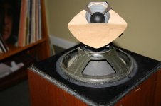
inverted cone driver ought to have different dispersion compared to normally mounted driver (again consider box speaker or a very wide OB) because of the convex radiating surface.
some OHM Walsh speakers use this type of driver mounting to extend the omnipolar radiation higher in the freq range (pic).
and as you say, the spider and magnet would also affect the radiation at higher freq.
Attachments
I have measured some small and medium mid(woofer) cones also from backside. Directivity is total mess, unpredictable and uneven. Total radiated power equals frontside obviously but... The spider and magnet structure mess everything above say 1000Hz. Just try it!
I have measured some small and medium mid(woofer) cones also from backside. Directivity is total mess, unpredictable and uneven. Total radiated power equals frontside obviously but... The spider and magnet structure mess everything above say 1000Hz. Just try it!
Again my question is
Can we use that "mess" in our benefit?
ie. to reduce beaming and or comb filtering of multiple mid arrays
^Wouldn't it be easier to just use minimal diameter drivers per "way" to get smooth and wide dispersion?
Well then we encounter the distortion challenge... But if we discuss only normal home environment/sound levels, there should be no problems with that. Examples - Yamaha NS-5000, Magico, Avalon, PMC, Harbeth, etc. 3-way speakers with 3-5" midranges and dome tweeters.
Well then we encounter the distortion challenge... But if we discuss only normal home environment/sound levels, there should be no problems with that. Examples - Yamaha NS-5000, Magico, Avalon, PMC, Harbeth, etc. 3-way speakers with 3-5" midranges and dome tweeters.
The patent and measurements in it are just rubbish.
Rubbish how? Are you implying that the measurements are false / fabricated?
The 4-driver flower is acoustically like a single 15" [...] Sure it is different above 500Hz
Yes. This appears to be the point.
Attachments
^A quadruple (or any group of widerange transducers) has similar directivity as a single driver of same outer diameter. The patent application and controllees just didn't know that. Poor understanding of the topic! It should be impossible to get a patent to a law/ phenomenom that is just basic physics!
I see what you mean. The patent is just a rotation of a basic array, so may not be sufficiently novel:
"Using this method, a typical speaker array may attain benefits disclosed herewith."
However:
"Embodiments of the present invention achieve this result by an advantageous arrangement of transducers."
The specific details of the "advantageous arrangement" seem to be the point of the patent.
To me, it is not immediately obvious how you would get the pattern shown in figure 22 rather than the pattern in figure 20. If literally nobody had produced or illustrated this benefit of skewing an array in this manner*, that implies it wasn't immediately obvious to anyone else, either.
Note that the patent is hella old, doesn't apply to DIY, and I'm not a lawyer, so I don't really have a horse in this race 🙂
*I believe a requirement of a patent is that it hasn't been made / described / illustrated publicly elsewhere
Last edited:
With a loudspeaker simulation software it is easy to test jos multiple driver groups behave. They were not so easily available 10 years ago.
There is a way to get multiple drivers to behave as a point source without beaming and lobing problems. For a clue, look at my signature 🙂
BTW, one of the drawings in the Synergy patent shows a relatively large number of drivers surrounding a central driver on a baffle. Basically, a baffle is a 180H x 180V horn. Its much easier to get the drivers close enough together when they are offset mounted on the sides of a less wide dispersion horn.
BTW, one of the drawings in the Synergy patent shows a relatively large number of drivers surrounding a central driver on a baffle. Basically, a baffle is a 180H x 180V horn. Its much easier to get the drivers close enough together when they are offset mounted on the sides of a less wide dispersion horn.
- Status
- Not open for further replies.
- Home
- Loudspeakers
- Multi-Way
- Has anyone tried these MMTMM configurations?