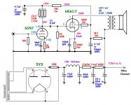
The power tranny is a hammond 272BX. It's 600VCT @ 100mA, 5V @ 2A, and 6.3V @ 3A. I have the recifier tube, then 15uF cap, then a big 15H choke, then 40uF. My output trannies are custom wound from another amp, so im not sure about them, but they're twice as big as the power tranny and they weigh a metric sh*t load.
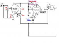
But i'm hesitant to start over with a new design; honestly, this one somehow sounds pretty good the way it is. I want more bass. And to get rid of this godforsaken input cap. SO: from the original schematic, can i just replace EVERYTHING between the input jack and the input tube (R1, R2, R3, C1, ect.) with ONLY a normal 10k pot? (please say yes, lol) Maybe the music's bass would be forgiving and come back.
But i'm hesitant to start over with a new design; honestly, this one somehow sounds pretty good the way it is. I want more bass. And to get rid of this godforsaken input cap. SO: from the original schematic, can i just replace EVERYTHING between the input jack and the input tube (R1, R2, R3, C1, ect.) with ONLY a normal 10k pot? (please say yes, lol) Maybe the music's bass would be forgiving and come back.
Jaencer,
The BASS issues are primarily due to the capacitances he has in the schematic.
1). The Ck (cathode bypass) on the power tube has an F3 of 24hz!! This means that the bass is down -3db (1/2power) at 24hz and does not get "flat" until 48hz, on top of that many phase issues go further up into the frequency range.
Increase the value of C3 to like 220uF or more (Rat Shack sells electrolytics for this cheap) and voltage over 25VDC is OK.
2) The coupling cap into the output stage C2 along with the 220K grid leak R4 again filter bass, the F3 there is 15hz,
Replace C2 with a .1uF cap this will restore response down to 14hz with 3db down @ 7hz
3) R8 can be removed altogether along with its connection (see attached) this is some sort of "local feedback" not sure that it is needed I removed that part of the circuit on my amp.
4) As I see it C5 is ridiculously low, it looks like an RC filter limiting response. What I would do is split up R6 into R6a & R6b. Make R6a 15K and R6b 200K. Then change C5 to like 4.7uF or so 300VDC as shown in the attachment. You will loose just a bit of gain but increased response and decoupling the B+ from the output is much more important. (we will fix the gain issue next)
5) Add the 2K cathode resistor (Rk) as shown in my attachment.
This will Bias the 6SN7 @ about -2V. This will make the input voltage gain about 13. If this is not enough to drive the ouyput fully (it should be) you can bypass the Cathode resistor on the 6SN7 with a capacitor. You could use the 20uf you replaced on the output capacitor.
All these changes have sound reasoning behind them. IMHO it should make this a "workable" amp. Email with any questions.
BTW, you should really check the impedance on the OPT's. Do you know how?
A simple way is to feed the primary a low voltage AC source like maybe 12.6 volts from a filament winding. Measure the AC voltage going in accurately and the AC voltage out the secondaries.
So example:
12.6 volts input to primary
400 mV (.4V) output
so the turns ratio is 12.6 / .4 = 31.5
Impedance ratio is Turns Ratio Squared (31.5 x 31.5) = 992.25
So an 8 ohm load on the secondary would result in the primary impedance of 8 x 992.25 = 7938 or 7.9K
I am sorry if any of this is redundant and you already know it, I am out of work right now so playing with all this is "Fun" for me.
After making these changes let me know how it sounds. They are easy and cheap. I myself really need BASS for it to sound musical, I spent many years in Car Audio and maybe my lower frequency hearing is weak. (Actually I know it is along with high frequency).
It sounds like you could have a nice little amp here seeing as how you have some good Iron.
You can feel free to email me with any ??. This has rekindled my interest in this old design, I might just bring the old chassis out of retirement and play with it using some using 6W6's and 6SL7's for an Ipod amp for my 9 year old daughter.
Attachments
Just finished building, and now am listening while pondering why this amp is so stubborn.
I put on some blues first, and the HIGHS sound better 😕 it was immediately noticable, the mids are clearer. (Also there's more mains hum, but low enough not to mind)
So i put on some 2pac and was shocked that my poor bass is crunching now . When the volume is at a reasonable level, even, it will take fat bass hits, chew them up, and spit them loudly out. Even with civilized music, turn it up at --hard day-- level and it crunches left and right where it didnt before.
With the volume down, the speakers dissapear into the sound better with this design. Almost would be a good headphone amp (or good for highs in a bi-amp system)
Not sure what to do. I'm willing to change the output tubes... or something... the way it stands now, the original was more functional, but if i change it back i'll miss the beautiful hi's. Maybe if it were changed back but with a bass filter ( i have a good Sub).
From listening, it seems that the best solution is a filter.
Less bass is better than crunchy bass.
I put on some blues first, and the HIGHS sound better 😕 it was immediately noticable, the mids are clearer. (Also there's more mains hum, but low enough not to mind)
So i put on some 2pac and was shocked that my poor bass is crunching now
. When the volume is at a reasonable level, even, it will take fat bass hits, chew them up, and spit them loudly out. Even with civilized music, turn it up at --hard day-- level and it crunches left and right where it didnt before.With the volume down, the speakers dissapear into the sound better with this design. Almost would be a good headphone amp
(or good for highs in a bi-amp system)Not sure what to do. I'm willing to change the output tubes... or something... the way it stands now, the original was more functional, but if i change it back i'll miss the beautiful hi's. Maybe if it were changed back but with a bass filter ( i have a good Sub).
From listening, it seems that the best solution is a filter.
Less bass is better than crunchy bass.
and the shunt resistor can be a pot, that way the music can be unmessed with for tracks that dont crunch!
As I think this over there could be a couple issues.
1🙂 To do this correctly we really need to know the OPT's impedance and DCR.
2🙂 What is the source you are feeding this with?
3🙂 The 10K pot if it is audio taper may be too small. The variation from medium to FULL volume may be so small that you are getting into the "overdrive" before you can stop the control.
4🙂 Check the voltages at the 6K6 plate and 6SN7 plate. Let me know what they are. We might want to check the operating points of the 6K6's in relation to your actual measurements of the OPT's.
5🙂 We might want to add screen grid resistors.
My best guess as to the crunchy bass is this:
The original schematic using a 6SN7 had very little gain. We now have enough gain to drive the 6K6 grids positive and stop current flow on the negative side at FULL OUT on the pot. Since this is SE that is a NO NO.
Example if the Bias is -20 and the negative swing from the 6SN7 is -20 we are driving the tube to cutoff. (would work in PP but not SE)
I never bothered to actually check the Operating Point of the 6K6's that Wes intended. Like I said his descriptions lack a lot of information.
Ok I went back to his website and I found something BIZARRE.
His voltage check show me something weird!
He indicates that the voltage drop across R9 should be 47 volts. This means a current thru it of 65.2mA. He also shows Plate voltage for the 6SF5 of 90V after a 220K resistor. That means about 1mA. So 65.2-2mA leaves idle current in the 6F6's of 63mA or 31.5 each. He also shows a Bias of -10 Volts. When I look at the pentode curve for the 6K6 -10 volts bias is NO WHERE NEAR a plate voltage of around 240-260 and current of 30mA???
This is also not figuring in any current for the screens?
The Class A spec's for a 6K6 indicate a screen and plate voltage of 250V with a total current of 37.5mA @ Idle.
I plugged in the numbers from above into PSUD with your tranny, caps and choke. I need to know the DCR of the choke, but it seems that we are WAY over voltage. To get to 270V the choke needs a DCR of 750 ohms.
This is all a little weird.
Get me the DCR of the choke, the impedance of the OPT along with its DCR. From there we can re-calc all the values and get you to the Spec'd Operating point. I think we will be sounding good then.
Tom Bavis said:Try putting the feedback resistor back... (R8).
That is a good idea but we still have the issue of Operating points that are all over the place. What is troubling me is that the information on the original schematic seems to look like it is purely out of the Tube Manual but the voltages just don't add up.
See my post about acquiring actual specs on his choke and trannys.
Let's get the thing "idling" properly as it is built now. Then we probably will need the feedback since at best we are looking at 11% THD with no feedback. Wes's schematic and write up were very attractive to me for my first build but with hindsight of a few years experience I can see why I hated it the first go around.
I suspect that his as built voltages are really high. (I don't see a 15H choke having a DCR of 750) Which troubles me even further since plugging in Wes's numbers gets me more along the lines of the Spec from RCA??? But not Wes's Bias and voltages. Another thing that troubles me is the overall topology of feeding the screens directly.
Unfortunately my experience with Pentodes is limited so we kind of have a "blind leading the blind" situation. But since I have nothing but TIME (being unemployed right now) I thought I could learn right along side Jaencer. Since I do have a little bit more under my belt we make a good team.
I also have an "Ulterior Motive" in I have a few 41 tubes laying around. Since they are identical, this will be my design for that amp.
Nothing like having someone do your prototyping for you!! LOL
lol works for me! well I got a gang of data for ya, and picked up some new resistors R2, R3, and R8 in case we decide they should come back.
here goes
SOURCE: a computer sound card, m-audio audiophile 192, which has output capacitors (no DC to worry about) and very low Z
15H CHOKE DCR: 16.9 ohm
OPT Z (using 8ohm secondary): [primary : 8ohm secondary] = 189.48 : 1
OPT DCR: primary is 18ohm, secondary is 0.55 ohm (seriously)
after running for long time, the PT gets hot, but the OPTs are actually cold.
I was told by a wise old sage today to make C6 much smaller (he said 1uF), since the 15 henries should be doing the grunt work.
he said that my hum may be coming from the big E-field surrounding that first cap, because the bigger it is the more current goes through it...
and this current is dissipated not only as heat but an e-field right into the tubes causing hum.
(he also told me to go get some more efficient speakers- problem solved)
my speakers are KRK ST6 studio monitors (hey I'm a student, and they sound great) -> Sensitivity = 1W @ 1m: 89dB
...maybe a real low power tube amp will never drive them properly. it's worth a try.
anyway what do you say I add R2, R3, and R8, trade C6 for something smaller
or do the numbers staunchly object?
It's starting to seem like the one or two watts that this system puts out is just badly paired with an aluminum driver.
Your design opened up the bass, revealing the reason why the bass was filtered out of the original design. It's clear why they cut it out, but maybe there's a better way than a lousy 4.7nF input cap.
Also, this schematic came from a commercially manufactured unit (*sigh*) so all the caps were probably low value because that is cheaper (not better) (also explains the supply resistor and lack of a choke)
Long story short, it sounds GREAT at low volumes, therefore, why not bring the volume UP simply by a more fitted speaker.
But don't let me discourage you from working some more schematical magic.. schemagic lol
you're input has been invaluable
notes:
first test: gave primary 16.4 VAC, 8ohm secondary reads 1.191 VAC
this yields [primary]:[secondary] = 13.77:1
second test: primary reads 216.4 VAC, after giving secondary 15.73 VAC
this yields [primary]:[secondary] = 13.76:1
ave. turns ratio is 13.765:1, impedance ratio is then 189.48:1 for [primary : 8ohm secondary]
how does it look?
hopefully the voltage on the tubes wasn't too high.. they were on for a while
maybe on the input, a 4.7uF in series, and a 470ohm shunt resistor (or pot), for 72 Hz cutoff (or less)
maybe on the input, a 4.7uF in series, and a 470ohm shunt resistor (or pot), for 72 Hz cutoff (or less)
Jaencer,
Just got back from my nieces Basketball Game, (she lost) I will look over the numbers and get back to you. 89dB is FINE for this amp unless you plan to drive the neighbors crazy.
Especially if you're in a dorm room or small apartment bedroom.
I will post up my findings and also my "41" SE amp. I spent the whole afternoon yesterday playing with it I just need OPT's and Sockets and I will have an "OLD SCHOOL" amp. UX280 rectifier, 76 input/driver, 41 Power tube. If I could just get over the fear of DHT's I would go all the way and use the two NOS 45's I have!!
Mike
BIG PROBLEM!!!
The OPT impedance into 8ohm load (your speakers probably average 6) is ONLY 1500 OHMS!! TOO LOW!
Do you have any other OPT"S?? something more like 6 to 8K? even small ones will do. (for a student I recommend Ebay if you don't have any on hand)
Aside from the OPT's I will look at the PSU. I think we found most of the issues right here though.
I am surprised we get anything at all out of it and the low impedance explains the HOT PT! The current flow is huge. Were the plates of the tubes glowing?
I have some smallish 6V6 type OTP's they have a DCR of 450 so I will base my schematic on that DCR. Let me know what you can source and we can modify if need be.
jaencer,
My daughter messed up my Ebay Account (bought stuff and didn't ask me to pay for it and I got suspended) I will pay you to buy me 2 of them at a little profit for you. I can send money via paypal if you would ask the seller for price on 4 shipped to you. I will pay for two units plus the shipping to you and then the shipping to me plus $5??
My daughter messed up my Ebay Account (bought stuff and didn't ask me to pay for it and I got suspended) I will pay you to buy me 2 of them at a little profit for you. I can send money via paypal if you would ask the seller for price on 4 shipped to you. I will pay for two units plus the shipping to you and then the shipping to me plus $5??
Ok,
After reading all of the other posts Jaencer you will probably be dizzy.
I "re-worked" the schematic to a format that I like much better.
If you obtain some more suitable OPT's (the ones I posted are so cheap that they are worth a shot!) try out this layout.
Pay close attention because a lot of values and the layout have changed. This is more of a "conventional" pentode SE layout.
We can experiment with feedback later. Your biggest problem was the voltages were WAY TOO HIGH with your PS and the LOAD WAY TOO LOW. This explains all the distortion, the hot PT and lack of bass.
I threw this together so anyone of the more experience users out there please check it for me.
This is very much like the 41 SE I am planning to build.
Attachments
coldcathode said:BIG PROBLEM!!!
The OPT impedance into 8ohm load (your speakers probably average 6) is ONLY 1500 OHMS!! TOO LOW!
Do you have any other OPT"S?? something more like 6 to 8K?
sh*t.
that makes me sad, these trannies are a shame not to use. I called the wise old sage and he told me to just use the 4 ohm taps- i'll test them right away. He also told me to try 6V6 in place of 6K6 because 6K6 likes 7600ohms and 6V6 likes 5000ohms (closer, at least) (AND the 6V6 tubes suppose to be louder)
coldcathode said:I am surprised we get anything at all out of it and the low impedance explains the HOT PT! The current flow is huge. Were the plates of the tubes glowing?
Nope... and man, for tons of current and voltage flow, there wasn't much bass to show for it. maybe this power is why it sounded better.
coldcathode said:jaencer,
My daughter messed up my Ebay Account (bought stuff and didn't ask me to pay for it and I got suspended) I will pay you to buy me 2 of them at a little profit for you. I can send money via paypal if you would ask the seller for price on 4 shipped to you. I will pay for two units plus the shipping to you and then the shipping to me plus $5??
Sure man, no prob (but if i was you i'd just make my girlfriend or buddy set up a quick account and use it, to save cash). i'll also see if i can't grab 2 or 4 trannies at some of the multiple local san diego shops, and send you a couple. nice transformers are easy to come by for cheap round here
Originally posted by coldcathode
I "re-worked" the schematic to a format that I like much better.
If you obtain some more suitable OPT's (the ones I posted are so cheap that they are worth a shot!) try out this layout.
Pay close attention because a lot of values and the layout have changed. This is more of a "conventional" pentode SE layout.
We can experiment with feedback later. Your biggest problem was the voltages were WAY TOO HIGH with your PS and the LOAD WAY TOO LOW. This explains all the distortion, the hot PT and lack of bass.
I threw this together so anyone of the more experience users out there please check it for me.
Ok, this is another complete re-make-- anything for the sake of not having to buy a commercial unit, i guess. But it does sound like a LOT of changes happening at one time. To me, listening to the amp, it doesn't sound like we are THAT far off, maybe a few changes here and there.
*note* in the schematic you have a 15H choke DCR of 160, but measured DCR in it was 16.9
- So we need a lower voltage... looks like the supply resistor is needed 🙁 oh well
- 6V6 tubes may prove to be little BASS first aid kits, and also better fitted for this circuit, i'd like to try them
- I'll measure the OPT 4ohm taps impedance, i'm quite attached to these iron bricks. maybe you're schematic and mine will differ
- There's a whole lot of stuff changed in your new schematic. Thing is, i really really like the sound of the old one- you probably would too. i'm fresh from the transistor crowd, so you're changes are unclear to me except that they are extensive. I trust the changes would work, just not sure whats changed. is this all to fix the voltage levels and accommodate new iron? will it sound different?
how about switching to the 4ohm OPT taps, adding a 470ohm power resistor after the choke to bring down the voltage, and plugging in some 6V6 tubes. if it works i'm throwing a fat party
i'll set forth on the new parts scavenger hunt, let me know which of them to install, oh and i'll keep an eye out for iron (yesterday i saw 6.3V 1.5A heater transformers for 4 bones each)
well, to update, i did a test... i added a 470ohm power resistor to the supply to bring down the B+, and I changed the tap to the 16ohm setting as "old man wisdom" from the antique radio store told me to do. Also, i changed the tube bias resistor from 330k to 450k.
It sounded worse. bass still crunches, and the image is gone. it works, but the magic is dead.
Next, i put in 6V6 tubes- the bass is much better, but the highs are worse
I'm considering going back to what i had originally... if the tubes die from overvoltage, at least they will have served me well. not sure yet
- Status
- Not open for further replies.
- Home
- Amplifiers
- Tubes / Valves
- Has anyone built this amp?