Hi All,
My first post here.
I found the "50C5 for a Newbee" thread very helpful. Thank you TubeLab.com
The schematic inside my H303A shows R4 going to ground. But when I open it up an look, it is soldered to "B". I thought this was done by a previous owner as I also see new capacitors (C1 & C2) the rest are original.
Currently I get no signal from the 50C5 plate (pin 7) but has signal going into pin 2. Pin 7 is a flat 2 volt AC. Pin 5 ac signal is identical to pin 2.
I will run some test with my scope (also vacuum tube) and post the findings.
Thanks,
Rich
Here's a better schematic, a little more readable. It looks to me like both schemos have made the mistake of having R4 to ground. You need voltage on the screen for that tube to work. I think it's correct to be hooked to "B"
What DC voltage to you have on pin 6 and 7 of the 50C5? Also, check "A source" and "B source" of your power supply. Pin 7 should be a few volts less than "A" and pin 6 can be quite a bit lower maybe 15- 20 volts or so. Or it might be only 5v. Just mostly a guess since there are no voltages given. Also, check your heater voltage for that tube as well. Should be around 50v. Pins 3,4 for this.
Edit: Welcome to the forum!
View attachment harmony_h303a.pdf
Last edited:
I agree, R4 needs to connect to B, not ground.
Boobtube covered it, you need to verify the power supply voltages are present. If you have R4 connected to ground, then the power tube will not conduct, so having good B+ at pin 6 is crucial. But then so it is at all the other points using B+. B+ will be low, as the main filter caps are all 150v types, I would not expect B+ to be any higher than that.
Power tube cathode resistor R7 needs to have some voltage dropping across it, if the voltage across it is zero, then the tube is not conducting.
All tube heaters must be glowing, are they?
I think Enzo has a typo. If R4 is connected to ground, the preamp tube won't conduct, not the power tube. The power tube also needs screen voltage as does any pentode and the screen(pin 6) of the 50C5 is connected to "B" which is correct.
Another clue to back up Enzo on the voltages for the 50C5 is that the data sheet gives 150V as the max plate voltage and 130v for the screen, so yes, expect around maybe 120-130VDC on the plate and around 10 volts less on the screen.
I also agree with Enzo about checking the heaters and 12AU6 plate and screen voltages. It looks like the plate will be around 90v and the screen maybe half of that. It's really hard to tell without voltages on the schemo. Sometimes educated guesses will have to do.
One last thing, as you can see from the schematic I linked you to, pin 2 and 5 of the 50C5 are connected, so don't worry about both of them having signal present.
Last edited:
I was using the same drawing as above, and yes, I did mis-state power tube when I meant preamp tube. The tube with R4 connected, let's call it that then.
Thank you so much Boobtube and Enzo.
50C5 Pin 6= 120 V DC, Pin 7 - 118 V DC, A = 128.8 V DC, B = 120.2 VDC.
R4 is connected to B. I tested with a calibrated Fluke 87 V.
All tube are getting correct power and glow. I checked across pins 3 & 4.
When I touch with my finger - between C3 and C4 I can hear a buzz.
Sorry for the poor schematic. I took the pic inside the cabinet. Another type-o. It shows V2 is a 50c6 instead of 50c5.
I got this amp 15 years ago along with a Harmony H400A (widow maker) for 10 bucks a piece. I just recently remembered I had these stashed away in my computer room and thought I would fix them up while it was too hot out to work on my old cars out in the shop.
Here are more photos. I LOVE anything vacuum tube. even my guitar tuner is tube, It's a CONN and works perfect. 🙂
Harmony H303A Tube Amp Story by TXCurbster | Photobucket
What DC voltage to you have on pin 6 and 7 of the 50C5? Also, check "A source" and "B source" of your power supply. Pin 7 should be a few volts less than "A" and pin 6 can be quite a bit lower maybe 15- 20 volts or so. Or it might be only 5v. Just mostly a guess since there are no voltages given. Also, check your heater voltage for that tube as well. Should be around 50v. Pins 3,4 for this.
50C5 Pin 6= 120 V DC, Pin 7 - 118 V DC, A = 128.8 V DC, B = 120.2 VDC.
R4 is connected to B. I tested with a calibrated Fluke 87 V.
All tube are getting correct power and glow. I checked across pins 3 & 4.
When I touch with my finger - between C3 and C4 I can hear a buzz.
Sorry for the poor schematic. I took the pic inside the cabinet. Another type-o. It shows V2 is a 50c6 instead of 50c5.
I got this amp 15 years ago along with a Harmony H400A (widow maker) for 10 bucks a piece. I just recently remembered I had these stashed away in my computer room and thought I would fix them up while it was too hot out to work on my old cars out in the shop.
Here are more photos. I LOVE anything vacuum tube. even my guitar tuner is tube, It's a CONN and works perfect. 🙂
Harmony H303A Tube Amp Story by TXCurbster | Photobucket
Last edited:
What bias voltage do you have on pin 1 of the 50C5? It should be around 8 VDC or so.
Also, check the resistance sweep of the vol. control. Should be audio taper 500k ohm.
The OT primary isn't shorted, otherwise you wouldn't drop that 8.8 volts from "A".
Are you sure you don't have pin 6 and 7 voltages mixed up? The screen should be lower than the plate. "A" and "B" of your power supply look correct.
Last edited:
Are you sure you don't have pin 6 and 7 voltages mixed up? The screen should be lower than the plate.
Ideally we want the plate higher than the screen, but it is quite common in small one lung amps like this to be upside down in that regard. Ther are a lot of small basic amps that connect the B+ to screen directly, then also to the OT, and through that to the plate, meaning at idle the plate will always be lower than the screen.
If your 8v prediction on the cathode is correct, then about 40ma would be flowing through that plate. I gave 4ma to the screen just to make it even. So since there is about 10.8v dropped across the OT primary, then at 40ma, the DC resistance of that primary ought to look like 280 ohms. That sounds reasonable to me offhand, and would explain the plate being a trifle lower than the screen. We can recalculate that when we get a real reading on the cathode.
Your complaint is no signal passing through the amp. You mention loss of signal at pin 7 of the power tube, yet touching C3/4 makes hum out the speaker, so the thing is amplifying in the output stage. it may not be 100%, but if you heard that hum touching a cap, then it is functioning.
Hum injection is a simple but useful way to find where the signal path is interrupted. I often use a small screwdriver rather than my finger. Also, if I unground the black probe from my meter, then the red on becomes a nice antenna for hum to use as injection.
So if C3/4 hums, then move back to the plate of the V1, pin 5. Get hum touching there? Move further back, touch the grid of V1, pin 1. Does that hum? Then do each end of C1.
Do you have B+ on both plate and screen of V1, the preamp tube?
Pin 1 reads 7.78 V DC
Pin 6 is reading higher than 7.
Resistance sweep is 410 K OHMS to 40 OHMS.
Pin 6 is reading higher than 7.
Resistance sweep is 410 K OHMS to 40 OHMS.
V1 Pin 5 and 1 when touched produce an almost inaudible tic.
I have 6 12AU6 tubes. I tried them all with the same results. They all tested good on my tester also.
Could it be one of my less than kosher soldering points around V1?
I have 6 12AU6 tubes. I tried them all with the same results. They all tested good on my tester also.
Could it be one of my less than kosher soldering points around V1?
Using my guitar as a signal generator I see 42 mV AC when strummed and 19 mV AC still on V1 pin 1.
Between C3 and C4 202 mV AC strummed, 156 mV AC still.
After C4 or Pin 2 on V2 222 mV AC strummed, 156 mV AC still with the volume up all the way.
Between C3 and C4 202 mV AC strummed, 156 mV AC still.
After C4 or Pin 2 on V2 222 mV AC strummed, 156 mV AC still with the volume up all the way.
V1 Pin 5 and 1 when touched produce an almost inaudible tic.
I have 6 12AU6 tubes. I tried them all with the same results. They all tested good on my tester also.
Could it be one of my less than kosher soldering points around V1?
Definitely possible. Check all solder joints and make sure that the cathode and pin 2 have a good connection to ground.
We really need those DC voltages for that 12AU7 for the plate and screen. The AC voltages don't mean much if you don't have the proper static(quiescent) conditions. While you are at it, check the bias voltage on pin 1 too. You have the old grid leak bias method, so different tubes might give different voltages. If it seems way off, you could check the value of that 2.7 meg grid leak resistor.
When checking an amp that doesn't work, it's best to get the DC static(no signal) voltages to make sure the proper conditions exist for the tubes to operate. Check power supply, plate, screen and bias. DC voltages for all of these.
Last edited:
Sorry, meant 12AU6 voltages. Not used to that particular tube for guitar amps. That bias voltage should be maybe a volt or so depending on the plate voltage.
Resistance between chassis ground and V1 Pin 1 = 2.723 M Ohms.
R3 off Pin one reads 2.7 M Ohms measured directly on that resistor.
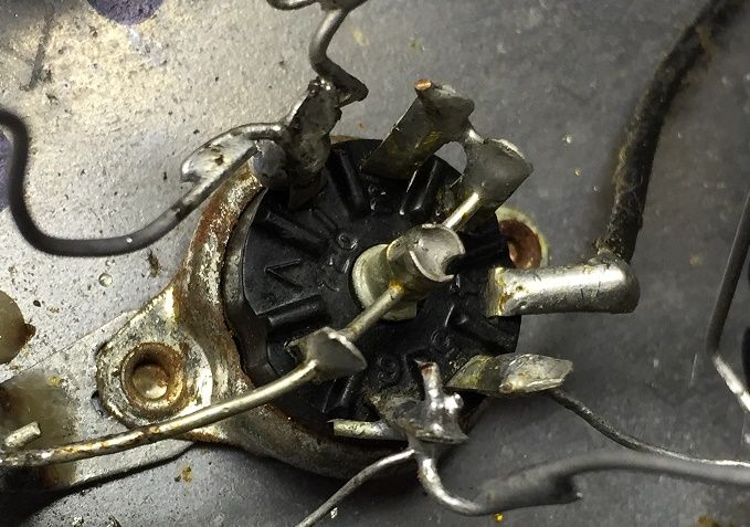
V1 Pin2 reads 0.5 Ohms. Pin 2 has a solder bridge to Pin 3.
V1 Plate (pin 5) reads 121 V DC.
V1 Screen grid 2 (pin 6) reads 22 V DC.
BIas Voltage at Pin 1 : I am not sure how to test this.
+ probe on Pin 1:
Pin 1 to Pin 2,3,7 or chassis gnd = -0.8 V DC.
Pin 1 to Pin 4 = -0.83 V DC.
Pin 1 to Pin 5 = 120 V DC.
Pin 1 to Pin 6 = -17.7 V DC.
R3 off Pin one reads 2.7 M Ohms measured directly on that resistor.
V1 Pin2 reads 0.5 Ohms. Pin 2 has a solder bridge to Pin 3.

V1 Plate (pin 5) reads 121 V DC.
V1 Screen grid 2 (pin 6) reads 22 V DC.
BIas Voltage at Pin 1 : I am not sure how to test this.
+ probe on Pin 1:
Pin 1 to Pin 2,3,7 or chassis gnd = -0.8 V DC.
Pin 1 to Pin 4 = -0.83 V DC.
Pin 1 to Pin 5 = 120 V DC.
Pin 1 to Pin 6 = -17.7 V DC.
That 22v on the screen seems low. Generally from what I've seen, it's higher than that, somewhere around half of the plate voltage or more give or take. 121 volts on the plate is good. I haven't worked on many pentode based amps, so hopefully Enzo will weigh in.
The .8 volt bias should be OK. It could be higher but with the grid leak bias you never know for sure.
Maybe check the value of R4 and check that you have 12 volts AC for heater voltage between pins 3 and 4.
Also, it looks like whatever is hooked to pin 1 has been replaced, either R3 or C1. Make sure the rest of the connections associated with that are good.
Last edited:
- Status
- Not open for further replies.
- Home
- Live Sound
- Instruments and Amps
- Harmony H303A