Hi all
Perhaps someone much smarter than me can solve this on the Harmon Kardon 730 Vintage Receiver.
HK730 Service Manual
I have done a complete restoration and calibration - Nichicon HE KA, Panasonic FC, Wima MKS2 Caps, Bourns 3386 Potis, Vishay Resistors etc.
There is one problem remaining.
On the right channel, there is excessive DC for less than a second on startup, which causes the (added) protection circuit to activate.
At the Output Amp Speaker connector, the DC spikes up to about 7 volts (and buzzes the speaker), before the protector clamps.
After a couple of seconds, the DC stabilizes to <120mV, and so the protection circuit releases, and the machine operates normally.
Here’s the kicker.
I disconnected the U-connectors at the rear (signal path between the PreAmp and Power Amp).
I then fed an audio signal from Another Preamp directly into this HK730's Power Amp, and monitored DC at the speaker connectors.
No DC spike (max DC about 150mV), and no protection shutdown.
So, the Power Amp stage is just fine.
The problem is in the Right PreAmp, whose output (Green Wire at LP510 on the schematic) spikes up to 1.5VDC.
Here I’m lost.
I have traced the entire signal path on my scope, and it all looks quite normal (obviously), because the DC spike happens only right at startup, and doesn’t repeat, so it is incredibly difficult to trace under normal conditions.
Any hints at where to look?
Much appreciated
Menahem Yachad
CondorAudio
Last edited:
All I can think of is that you may have missed a leaky old electrolytic (or a resistor gone bad), mistakenly installed a much larger value, installed it the wrong way round, produced a bad solder joint or gotten a defective part.
In order to narrow down the problematic section further, unsolder one end of R519. If the problem then stops, it could still be C513/515 but not anything to the right of that.
C517 and C401 are quite large in value, so they would let quite a bit of low-frequency stuff through if it weren't blocked earlier on. Looks like C513 has a leading role there.
I'd also compare DC levels to the left of C517 and C518, maybe R531 has drifted. Sometimes these transistors (2SC1345) also fail and go leaky, the reliability of some NEC parts was not great.
I bet the old C401/C402 were dead as a doornail, right? (Assuming you bothered to ask a component tester.) Electrolytics that are pulled to ground on both ends do not tend to survive that long-term unless they are special low-leakage types, like the orange ELNAs you find in late-'70s gear... and those tend to be in the single µFs, not 100µ. Caps in problematic spots like that are best replaced with two of twice the value back-to-back (allowing a voltage to form between the ends and midpoint that counteracts dielectric layer degradation), and if you want to get fancy, connect the midpoint to a clean supply via a few Megohms for bias (not that easy here, as the power amp does not have the regulated and filtered preamp power rails that would be well-suited).
C503/504 appear to be in a similar position - Q501 would seem to be running at around 20 µA, so I can't imagine it'll have base current over 1 µA, probably less - so these caps would be seeing around 200 mV at best, probably below 100 mV. Could be a bit more depending on how much base current Q503 needs.
Last edited:
Thanks for your pointers.
Here's where I'm at.
1. At the junction of C503 and Q501 2SA844 Base, there is no spike at switch on - it's almost 0VDC constant.
2. At the junction of R515 and R519, it spikes to 2.4V and settles down at 1.3V.
3. At the same junction in the L channel, it rises to 1.3V, and stays there.
I have replaced R513, R515, R519 and R531. All appeared to check within tolerances, anyway. Therefore no change was shown after replacing the resistors.
I removed and checked Q501 2SA844 and Q503 2SC1345 with my Peak Transistor checker, and they check OK, hFe 380 and 520. However, I note your point about being leaky.
The closest substitutes I have in stock are 2SC2240, and 2SA970.
What do you think?
Firstly, I emphasize that ALL electrolytics have been replaced by high-quality Nichicon, Panasonic and Wima subs, and ALL have been installed correctly.
I have also resoldered all the PCB's, and there are NO solder bridges.
I replaced Q501 and Q503 (R-channel), and immediately the spike is now on the Left channel. The Right channel is absolutely calm.
So, I changed out the same 2 transistors (Q502 and Q504) on the L-Channel, but the spike is still there.
The spike disappears completely (in both the PreAmP and Power Amp sections, measured separately) if I disconnect the PreAmp from the Power Amp sections, by removing the U-connectors at the rear of the machine.
Any ideas?
BTW, how should the 2 coupling caps (which you mentioned) be connected?
If I take 2 x 220uF in series to make one 100uF bipolar?
Should the 2 negative poles be connected to the PCB, and the positive poles be joined together in between the 2 caps, or Vice Versa?
Menahem
I just purchased one of these a few weeks ago that has _not_ been recapped and it has a
very large turn on thump in one channel. I turn it on with both speakers off , wait about
20 seconds and then select the speakers and it works fine but certainly it needs a recap.
Very nice unit.
You can see for example that C529 and 530 are polarized as are C517 and 518 so there is
no need for using back to back caps.
You might try experiments such as grounding the + side of C513 and 514 to see if that
stops the problem to determine if it is upstream or down from that point.
What about the HP and LP filter stage?
It is possible that some component other than the electrolytic caps has gone leaky.
OK, problem solved, but I cannot give any exact single solution.
It was an incremental fix, as I monitored the power-on spike each time at the junction of R516 and R520 - Left channel.
Basic principles first.
1. Installed a network of soldered ground wiring from all the PCB's (which have push-on connectors - really poor idea) to a common point at the main rectifier PCB, with the 4 large filter caps.
2. Installed a modern Vishay F1772 310VAC X2 10nF suppression cap at the main AC Power-on switch.
3. Replaced a bunch of resistors around Q502 and Q504 (even though the originals were not really out-of-spec regarding their 5% tolerance).
Now specifics.
4. Replaced Q502 PNP 2SA970 and Q504 NPN 2SC2240 (again).
5. Replaced C517 and C518 with Nichicon EP BiPolar 100uF 35VDC.
That solved the problem to MUCH lower spike levels, but still present.
To finish up.
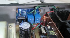
6. Installed a uPC1237-based protection PCB, which draws 60mA, and connected it to the 12VDC circuit at the bottom of the machine.
The receiver now powers on with no buzz.
Sound is superb.
It was an incremental fix, as I monitored the power-on spike each time at the junction of R516 and R520 - Left channel.
Basic principles first.
1. Installed a network of soldered ground wiring from all the PCB's (which have push-on connectors - really poor idea) to a common point at the main rectifier PCB, with the 4 large filter caps.
2. Installed a modern Vishay F1772 310VAC X2 10nF suppression cap at the main AC Power-on switch.
3. Replaced a bunch of resistors around Q502 and Q504 (even though the originals were not really out-of-spec regarding their 5% tolerance).
Now specifics.
4. Replaced Q502 PNP 2SA970 and Q504 NPN 2SC2240 (again).
5. Replaced C517 and C518 with Nichicon EP BiPolar 100uF 35VDC.
That solved the problem to MUCH lower spike levels, but still present.
To finish up.
6. Installed a uPC1237-based protection PCB, which draws 60mA, and connected it to the 12VDC circuit at the bottom of the machine.
The receiver now powers on with no buzz.
Sound is superb.
Attachments
- Status
- This old topic is closed. If you want to reopen this topic, contact a moderator using the "Report Post" button.
- Home
- Amplifiers
- Solid State
- Harmon Kardon 730 PreAmp output DC Offset, causing Power Amp Protection to activate