I have a Harman Kardon HK 3370, which I received from a family member.
It was damaged many years ago at a party where either the person cranked the volume too high or used it on some speakers without the right ohm setting - not 100% sure.
So, when it works it works fine.
The only problem is that if you unplug it then it will not turn back on when plugged in again.
You have to run through a reset option - hold the power button down and press 2 buttons on the front at which point the screen reads RESET. However, this only works occasionally as well.
It seems like if you leave it unplugged for a few days and then try resetting it works but it's temperamental.
Any ideas how I can fix this or what could be causing the problem?
https://goo.gl/photos/fQtw1Dxp9KpVWKic6
Just tried it again after it has been unplugged for weeks.
No speakers plugged in our other peripherals, just the ammo by itself.
Manual Power switch off, plug in, hold manual switch whilst pressing t-mon & CD button together. RESET appeared on screen then it turns off. Press electronic on button (separate button). Everything works fine.
Then I turned it off with the digital switch and then off with the manual button.
Wait 1 minute.
Turn on with the manual switch. Light comes on on digital switch but now unable to power on the screen and unable to reset with t-mon & CD buttons.
Without having the unit on my bench, I'd try changing C309 and C310 on the front board, C200 on the main board, and check R253 for its value at 10-ohm. These has to do with proper power supply (+5V) to the micro-controller and with the timing of power-on reset and release. Non-responding to controls can be a result of improper power-on reset timing.
Without having the unit on my bench, I'd try changing C309 and C310 on the front board, C200 on the main board, and check R253 for its value at 10-ohm. These has to do with proper power supply (+5V) to the micro-controller and with the timing of power-on reset and release. Non-responding to controls can be a result of improper power-on reset timing.
The symptom is that if I leave it unplugged for a while, say 48 hrs and then try the reset again, it works. The unit then remains working until the power switch (the full one not the standby) is turned off. Turning it on again, it does not then respond to a reset and I have to unplug it for 48hrs.
That sounds like something is storing a charge incorrectly?
Is that why the change of the capacitors?
Do I have to disconnect one end of R253 to test it or can I do it in place?
When capacitors lose capacitance, the timing of the reset at power-on changes along. When the power-on reset circuit is not able to hold the reset level long enough due to the changed timing, the micro-controller would not start up correctly and you end up with a non-responsive unit. When the capacitance loss is marginal there is this intermittent failure. Since the power-on reset only operates during hard power on, once the micro controller starts up properly it keeps working properly until hard power off.
And, no, you don't need to disconnect R253 to measure it. It's a low value resistor that in-circuit measurement gives good enough result in this case.
And, no, you don't need to disconnect R253 to measure it. It's a low value resistor that in-circuit measurement gives good enough result in this case.
When capacitors lose capacitance, the timing of the reset at power-on changes along. When the power-on reset circuit is not able to hold the reset level long enough due to the changed timing, the micro-controller would not start up correctly and you end up with a non-responsive unit. When the capacitance loss is marginal there is this intermittent failure. Since the power-on reset only operates during hard power on, once the micro controller starts up properly it keeps working properly until hard power off.
And, no, you don't need to disconnect R253 to measure it. It's a low value resistor that in-circuit measurement gives good enough result in this case.
Do you have a link to the schematic by any chance? Doesn't seem to be in the service manual I have.
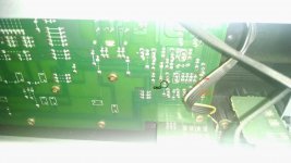
From the looks of the board, I have to completely unscrew it and take it out to do any soldering work. How can I discharge the capacitors first, looking at this pic, the only connection is underneath, which I cannot get to. There are a couple of 10,000uF, 63WV caps in the middle.
https://drive.google.com/file/d/0BwSNadx1dbgxNXcyTTBsSmlDUzNJb0dzUkJCd3FBS29pa3BB/view?usp=sharing
https://drive.google.com/file/d/0BwSNadx1dbgxaGRCX201b1dYUmY2RzZpelR6ZHR5WDh6TDFB/view?usp=sharing
https://drive.google.com/file/d/0BwSNadx1dbgxNXcyTTBsSmlDUzNJb0dzUkJCd3FBS29pa3BB/view?usp=sharing
https://drive.google.com/file/d/0BwSNadx1dbgxaGRCX201b1dYUmY2RzZpelR6ZHR5WDh6TDFB/view?usp=sharing
Before you remove the main PCB from the chassis, perhaps you can perform a simple test to see if a manually induced reset can make a non-responsive micro controller work. The power-on reset is on the front PCB. Try to locate Q301, and if it's accessible, short its Collector to GND through a 1K resistor momentarily while power is on and the unit is non-responsive to controls, and see if that turns it alive.
....and before any major removal you probably want to check all the supply rails have correct voltage. Most if not all of them are accessible by back-probing the connectors.
Before you remove the main PCB from the chassis, perhaps you can perform a simple test to see if a manually induced reset can make a non-responsive micro controller work. The power-on reset is on the front PCB. Try to locate Q301, and if it's accessible, short its Collector to GND through a 1K resistor momentarily while power is on and the unit is non-responsive to controls, and see if that turns it alive.
Seems hard to find as from the inside I can only see the back of the front board with no parts codes. Trying to look for 3 soldered areas...
Cannot take front off without detaching a whole load of cables.
https://drive.google.com/file/d/0BwSNadx1dbgxcnZ4R3NxUTRlMlU/view?usp=sharing
https://drive.google.com/file/d/0BwSNadx1dbgxdHpqVlVkXzlPNk0/view?usp=sharing
Last edited:
See picture attached. PCB layout of the front board is on page 107 in the manual. Check to make sure I had them right in the picture (I'm sure I did but please make yourself sure). Measure the voltage on the Reset line before the resistor jumper test. It must be at logic high level, or over +4V. If it's lower than that, say 3V or less, try to lift a lead of R303 or cut the foil between C309(-) and R303, and see if that can bring the Reset line voltage up.
If it is really hard to to get a resistor down there to jump Reset to GND, shorting Reset line to GND with a screw driver or a pair of tweezers is also ok. Be very careful working in a tight space and with power on and a long screw driver sticking around. Better sleeve it with some heat shrink tubing or tape the shaft up.
If it is really hard to to get a resistor down there to jump Reset to GND, shorting Reset line to GND with a screw driver or a pair of tweezers is also ok. Be very careful working in a tight space and with power on and a long screw driver sticking around. Better sleeve it with some heat shrink tubing or tape the shaft up.
Attachments
See picture attached. PCB layout of the front board is on page 107 in the manual. Check to make sure I had them right in the picture (I'm sure I did but please make yourself sure). Measure the voltage on the Reset line before the resistor jumper test. It must be at logic high level, or over +4V. If it's lower than that, say 3V or less, try to lift a lead of R303 or cut the foil between C309(-) and R303, and see if that can bring the Reset line voltage up.
If it is really hard to to get a resistor down there to jump Reset to GND, shorting Reset line to GND with a screw driver or a pair of tweezers is also ok. Be very careful working in a tight space and with power on and a long screw driver sticking around. Better sleeve it with some heat shrink tubing or tape the shaft up.
To short the resistor the GND, could I just connect the voltmeter leads to the right side of the reset and then tap the other lead to the chassis?
I have a 12k resistor soldered between 2 test leads so could use that.
Am I shorting the reset to ground or the collector of Q301 to ground?
Yes, you can, as long as you have made sure the chassis is grounded by checking continuity with a multi-meter.
The Reset I marked in the picture is hooked up to Q301 collector, they are on the same circuit node, so it makes no difference whichever spot you ground.
The Reset I marked in the picture is hooked up to Q301 collector, they are on the same circuit node, so it makes no difference whichever spot you ground.
- Status
- Not open for further replies.
- Home
- Amplifiers
- Solid State
- Harman Kardon - weird reset problem - HK 3370