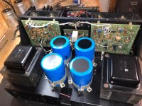
Disclaimer: I am a novice so anything other than novice speak will go over my head. Lol ……I have recapped my HK Citation 16A ( it was running super hot even at idle) and I have fired it up and it runs just warm at idle now. I also set the bias which was easily attained with adjusting VR2 on both boards. The problem is, that both left and right DC offset outputs can only be adjusted to no lower than .5 volts (1/2 a volt) with VR1’s adjusted all the way (inputs shorted). The fact that both boards are acting almost identically when vr1’s are adjusted might or might not be a hint? There are indications the amp has had the cover removed, but it did not appear to have any newer components in it than stock. Anyway, any ideas would be greatly appreciated.
electrotanya.com has the citation 16 service manual, please download. Don't be confused by the advertisements on the page for downloads of something else.Disclaimer: I am a novice so anything other than novice speak will go over my head. Lol …
You need to acquire some low voltage alligator clip leads to connect the black of the DVM to the analog ground. You should never use 2 hands to measure a voltage on a product containing >12 v. 25 v from one hand to the other can stop your heart. Measure two points with the red probe, write down the readings, and subtract to determine voltage across a component.
Wear no metal (jewelry) on hands wrists or neck. 1 v at high current through a ring can burn your flesh to charcoal.
Wear safety glasses with power on and soldering. Parts can exploded, solder can splash in the eye especially desoldering.
I would first check the +-12 v power supplies at C2 C3 to see they are nominal. Then check the +-10 v at the end of the pot VR1. Okay, then I would probe probe the stack R11 Q12 R20 CR5 -10v checking especially that CR5 is about 5 v. Zeners are a short life component. The transistor should be more than 1 v c to e. If that is okay, then probe +10 v CR6 R22 Q13 R27. CR6 should drop about 5 v and Q13 should be more than 1 v c to e.
I find packs of alligator clip leads at parts-express.com. Their bulb solder sucker I find useful. I like their variable temperature soldering iron, although you may already have one.
Thank you for the response. I am a very long time solder slinger, but the safety reminders are good for all of us, so thank you. I have all of the probes, so I’m good there. You have given me some areas to take measurements from, so I will start there and post the readings. I am sure it is a component or components that have gone out of tolerance, I just needed a place to start from, so thank you! 👍
Ok, I had other honey dos I needed to do and now I’m back on the 16. First off, I have the schematic, but they all e seem to be for the LED power meter model, and mine does not have the LED’s. Does this make a difference on other amplifier sections?
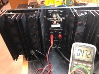
CR5 has obviously failed.1.08v on one end of zener cr5 and 1.29v on the other end.
Q5 e is supposed to be 9.5 DC and Q6 e is supposed to be -9.5. Suspect +10 v at junction of R5 R6 R7 CR10 is incorrect. Cr10 cold have failed. Same with -10v junction of R5 R24 R25 CR4 - CR4 could have failed. Alternately diodes CR1 CR2 could have shorted.
I don't have the 16A power supply page so I don't know where +-12 come from, but the filter capacitors there should read those values.
LED volume display or analog meter should not matter to the power amplifier unless the device is shorting the supply.
In replacing 1 W zeners, no penalty for replacing with 3 watt, or 5 watt if that is in stock. Same with 1n914, they could more profitably be 1n4148 or 1n4002 -3 -4 -5 or -6. The freight to get the parts from authorized distributors, ~$10 swamps the individual parts cost. Do not buy semiconductors or electrolytic caps from anybody but newark, digikey, mouser, alliedelec, or jameco.
Alternately, the filter caps at the +-12 supplies could have shorted. Or more rarely, the rectification diodes after the 12 vac winding. Extremely rarely, the 12 vac winding of the transformer is open.
Last edited:
Thank you gentlemen (I assume) 🙂. It looks like caps were not enough, and a full rebuild is in order.
Not supported by the limited data. More measurements in order. Not more parts willy nilly. Plus total rebuild usually injects a lot of bad solder joints into the product.Thank you gentlemen (I assume) . It looks like caps were not enough, and a full rebuild is in order.
You need to acquire an alligator clip lead to attach the black lead of the dvm to the analog ground, the center of the two rail filter capacitors. You cannot use speaker ground as analog ground, it is disconnected by a protection relay. Then check first, the +-12 rails at the filter caps. If those are okay, check the +-10 v points indicated. If those are bad, then $.30 10 v zeners are bad or a bad solder joint or broken trace. If the +-10 v voltages are okay, then the $.30 5 v zener you measured is bad.
If 12 v caps replaced already and 12 voltages not there, then 12 vac not going in the rectifiers, or rectifiers ahead of filter caps are bad, or you made a mistake.
The big money in a rebuild is the power transistors. Pros usually start with those without checking because bar bands blow up so many with dodgy speaker wiring or worn out speaker drivers. The dual gate Q1 is not available in leaded package anymore.
- Home
- Amplifiers
- Solid State
- Harman-Kardon Citation 16A dc offset too high