Full recap of the power supply and pre driver board. All new replacements for
TR603, TR606, TR605, TR625, TR626 and TR623 on the pre driver board. This has solved my popping issue that I posted in another post. Bit of a hand grenade to be sure.
My issue now is that the bias on the 2 variable resistors on the pre drive board has very little effect on the erratic behaviour of the DC voltage. The amp actually sound just fine. No distortion, not loss of signal. I am thinking that the problem is on the pre driver board. I don't think is the power supply. Perhaps the remaining transistors need to be yank.
Please jump in if any of you knowledgeable guys got a fix.
I have just got a Tek 2225 oscilloscope, but this will not be up and running until I get some recos on a signal generator. That's for another post🙂
Thanks.
SCHEMATIC HERE!
Harman Kardon 930 | Owners Manual, Service Manual, Schematics, Free Download | HiFi Engine
Biasing set's up the o/p devices and does not change offset voltages on the o/p stage.. some amps have 2 trim pots, one for setting offset voltage to near zero at the o/p end and the second one sets up the o/p transistors..
Biasing set's up the o/p devices and does not change offset voltages on the o/p stage.. some amps have 2 trim pots, one for setting offset voltage to near zero at the o/p end and the second one sets up the o/p transistors..
These trimers would be to set up the o/p transistors since the manual calls for 30mv per channel/trimpot. There is no adjustable offset in this receiver, sadly.
Service manuals can be a bit flaky. What you are doing is setting the DC across one of the 0.5 ohm emitter resistors to give 30mv which equates to 60 millamps. I wouldn't have any speakers connected because any DC offset will affect the reading due to current flowing in the speaker from the offset. Its normal for the bias to alter (quite a bit sometimes) with temperature. I would adjust it and then recheck and tweak after playing the amp to get it hot.
If you mean the true DC offset (the residual DC voltage across the speaker terminals) is varying then there is no adjustment for that. And if you mean the offset jumps about rapidly then that indicates problems with components such as caps (or perhaps semiconductors) but I'm not so sure you mean that anyway 🙂
If you mean the true DC offset (the residual DC voltage across the speaker terminals) is varying then there is no adjustment for that. And if you mean the offset jumps about rapidly then that indicates problems with components such as caps (or perhaps semiconductors) but I'm not so sure you mean that anyway 🙂
Service manuals can be a bit flaky. What you are doing is setting the DC across one of the 0.5 ohm emitter resistors to give 30mv which equates to 60 millamps. I wouldn't have any speakers connected because any DC offset will affect the reading due to current flowing in the speaker from the offset. Its normal for the bias to alter (quite a bit sometimes) with temperature. I would adjust it and then recheck and tweak after playing the amp to get it hot.
If you mean the true DC offset (the residual DC voltage across the speaker terminals) is varying then there is no adjustment for that. And if you mean the offset jumps about rapidly then that indicates problems with components such as caps (or perhaps semiconductors) but I'm not so sure you mean that anyway 🙂
Mooly it is the DC bias adjust measured on terminals TP1 and TP3, what HK calls the Bias Adjustment. DC meter on these terminals with a shorted input and an 8ohm dummy load I get erratic readings with seemingly no control from the variable resistors. Calls for 15mV on each channel. Hope that make sense.
A couple of things to look at and try.
1. Practical problem. Test points can be tarnished and covered in insulating grime. Solder flying leads to the test points and securely connect to the meter.
2. Measure and record the DC voltage across the vbe multiplier as you alter the pot. That's TR604 I think (the manuals a bit hand drawn 🙂) Its the transistor in the middle that connects the drivers together.
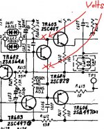
This one. It should vary up to around 3 volts as the pot is turned but be careful... if it is working then the output stage will start to get hot as you increase it.
That would be TR602 and TR622 I believe. Measure collector and emitter.
I had a bouncing dc on one channel of an HK430 I worked on once, varying continuously between -50mv and 200mv. I traced it to a bad transistor on the preamp board. Pull the jumpers in the rear of the unit and see if it goes away, if so, then it's the preamp.
I had a bouncing dc on one channel of an HK430 I worked on once, varying continuously between -50mv and 200mv. I traced it to a bad transistor on the preamp board. Pull the jumpers in the rear of the unit and see if it goes away, if so, then it's the preamp.
Worth a try🙂 I'll let you know what happens. I will be doing these tests, hopefully later today.
That would be TR602 and TR622 I believe. Measure collector and emitter.
You must measure the voltage across the device rather than from ground to it. Its the only way to get an accurate meaningful result.
You must measure the voltage across the device rather than from ground to it. Its the only way to get an accurate meaningful result.
There is no way of getting to the leads, real tight in there. Can I go from the solder side or is that going to distort the readings?
Anywhere that's electrically connected is OK such as R606 and C606 etc (just make sure you get the right ends) or across the base of the driver transistors.
Be careful, one slip or short and it all goes pop.
Be careful, one slip or short and it all goes pop.
Anywhere that's electrically connected is OK such as R606 and C606 etc (just make sure you get the right ends) or across the base of the driver transistors.
Be careful, one slip or short and it all goes pop.
🙁
If I am not going to ground with black probe do I then measure in a fashion that looks for a short in a transistor? In this case an NPN.
No, you are just reading and noting the voltage across that transistor as you turn the bias pot from min to max. If the bias isn't adjusting as you say then we need to look at what the bias voltage generator is doing. The voltage should vary smoothly to around 2.8 volts or so (that's four base-emitter junctions in series, the drivers and outputs, each at around 0.7 volts) at which point the output transistors should begin to conduct and get hot. So if thats not happening then we need to find out why.
No, you are just reading and noting the voltage across that transistor as you turn the bias pot from min to max. If the bias isn't adjusting as you say then we need to look at what the bias voltage generator is doing. The voltage should vary smoothly to around 2.8 volts or so (that's four base-emitter junctions in series, the drivers and outputs, each at around 0.7 volts) at which point the output transistors should begin to conduct and get hot. So if thats not happening then we need to find out why.
This is going to be tricky, holding 2 probes and moving the pot without shorting.
I should then hold the probes across C and E on the device and then turn the prop.
I'll try the helping hands on one probe.
Last edited:
If you are sure of the readings then that is nowhere near enough. Make a note of which way the trimmers adjust and set to minimum volts
Before we look at it closely, has the amp any previous history and have any parts been replaced ?
Before we look at it closely, has the amp any previous history and have any parts been replaced ?
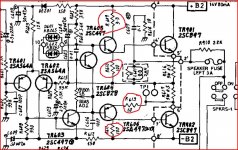
Reasons for not enough volts.
1. The current in the VAS transistor chain isn't enough... unlikely.
2. There is a faulty or incorrectly fitted driver transistor. Its worth checking the base-emitter volt drop across each. It should be around 0.65 volts.
3. One of the resistors marked is open circuit. If any are then the cause is likely to be a failed driver.
Attachments
- Home
- Amplifiers
- Solid State
- Harman Kardon 930 Bias Adjust