I have an A/D adapter to add an AUX port in my car. The adapter itself has a 2 gang potentiometer that adjusts the gain of the left and right channels of audio. The pot caused the left channel to drop out frequently. I never adjust the level, so I'd like to replace it with just a resistor. I found a volume level I liked and measured the resistance to be about 15k ohms. After desoldering the pot, I used a short piece of wire to determine which pins passed audio for each channel. The audio passed is super distorted. I tried placing a 15k ohm resistor inline, but then I don't get any sound. Unfortunately, the pot broke when I removed it from the board so I don't have much to work from. Any insights? Thanks!
Here are some pictures: https://goo.gl/photos/4t78x36yoCEwuZXu9
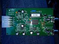
The PCB picture shows where the pot used to be. If you follow the two traces, you can see where the audio entered the pot. The annotated picture has the traces highlighted (white = left, red = right). The two green circles are what I think are the audio outs from the pot - this is where I get the distorted signal mentioned above. I have no idea what the orange pins do.
Here are some pictures: https://goo.gl/photos/4t78x36yoCEwuZXu9
The PCB picture shows where the pot used to be. If you follow the two traces, you can see where the audio entered the pot. The annotated picture has the traces highlighted (white = left, red = right). The two green circles are what I think are the audio outs from the pot - this is where I get the distorted signal mentioned above. I have no idea what the orange pins do.
I won't follow a link. You are probably best served by first replacing the pot and measuring it properly.
Sorry about the link - I just read the post about attaching pictures (they're attached to this post).
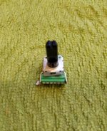
The replacement is a bit hard to find because it's 6 pins all straight across. There's not really much identifying information on the pot - B203 on the back is it. I know, I should have been more careful removing the pot. Next time I suppose!
The replacement is a bit hard to find because it's 6 pins all straight across. There's not really much identifying information on the pot - B203 on the back is it. I know, I should have been more careful removing the pot. Next time I suppose!
Attachments

You need to understand that a pot can act in a circuit as a potentiometer (tapped resistor - so three connections, same as two resistors) or a variable resistor (two connections - one resistor). In either case, it can used in a passive or active circuit.
When you say that you measured it as 15k is this the total resistance across the track, or the resistance of the side which you have established was used as a variable resistor, or the resistance of just one side of the potentiometer with the other unknown?
When you say that you measured it as 15k is this the total resistance across the track, or the resistance of the side which you have established was used as a variable resistor, or the resistance of just one side of the potentiometer with the other unknown?
Here is a datasheet of a similar pot.
http://media.digikey.com/pdf/Data Sheets/Panasonic Electronic Components/EVJC,EVJY.pdf
http://media.digikey.com/pdf/Data Sheets/Panasonic Electronic Components/EVJC,EVJY.pdf
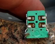
I solved the mystery thanks to the datasheet and some careful studying of pots!
The resistor needed to be placed between pins 1(audio in) and 3 (ground), with pins 1 (audio in) and 2 (audio out) tied together. The pinout matched the one linked in the above PDF. The pot in this case was used a variable resistor/volume control pot.
The resistor needed to be placed between pins 1(audio in) and 3 (ground), with pins 1 (audio in) and 2 (audio out) tied together. The pinout matched the one linked in the above PDF. The pot in this case was used a variable resistor/volume control pot.
- Status
- Not open for further replies.