hello everyone
i have trouble with capacitor discharge into an inductor.
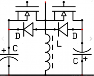
for schematic reference, i discharge the left one into the inductor, and than is charge the right one, negatively.
SO, my problem is that my RLC system is very under-damped and when i switch my IGBT on to discharge the left cap into the inductor, a voltage resonnance pike appears, about twice the capacitor voltage, at 15MHz, between the inductor edges. which, i think, is why my transistor breaks.
But, the other thing is that it breaks at Vcap = 70V, so the pike is around 140-150V and shouldn't break the IGBT, which is a 600V/ 160Apulse.
And the primary cap and its diode should cut it, what doesnt seem to happen, obviously, because it is really high frequency.
also, my igbt are switched really fast, i use a 9A gate buffer with Rgate = 4.7ohm
any clue ?
should i slow down my IGBT swtiching speed ?
should i use some more special diodes ?
does an other snubber could do the job ?
primary capacitor (left one in schematic): 2mF
cap resistance: ±500mohm
coil inductance: 168uH
coil resistance: 170mohm
IGBT: IRG4PC40UD
clamping diode: UF860
PS: in the schematic, i didnt have igbt symbole so i used mosfet... the left side is the "primary" cap which is discharged in the begining.
i have trouble with capacitor discharge into an inductor.
for schematic reference, i discharge the left one into the inductor, and than is charge the right one, negatively.
SO, my problem is that my RLC system is very under-damped and when i switch my IGBT on to discharge the left cap into the inductor, a voltage resonnance pike appears, about twice the capacitor voltage, at 15MHz, between the inductor edges. which, i think, is why my transistor breaks.
But, the other thing is that it breaks at Vcap = 70V, so the pike is around 140-150V and shouldn't break the IGBT, which is a 600V/ 160Apulse.
And the primary cap and its diode should cut it, what doesnt seem to happen, obviously, because it is really high frequency.
also, my igbt are switched really fast, i use a 9A gate buffer with Rgate = 4.7ohm
any clue ?
should i slow down my IGBT swtiching speed ?
should i use some more special diodes ?
does an other snubber could do the job ?
primary capacitor (left one in schematic): 2mF
cap resistance: ±500mohm
coil inductance: 168uH
coil resistance: 170mohm
IGBT: IRG4PC40UD
clamping diode: UF860
PS: in the schematic, i didnt have igbt symbole so i used mosfet... the left side is the "primary" cap which is discharged in the begining.
Attachments
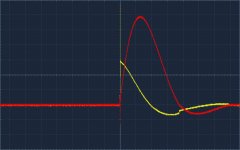
here is some waveform at Vcapacitor = 30V
the yellow one is the tension, and the red one is the current read from a 0.1ohm resistance, so its around 10A per volt
the first figure is the overall pulse
scales: 10V, 500us per division
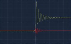
the second figure is a zoom around the switch ON, when the capacitor is discharging itself into the inductor
scales: 1V, 200ns per division
the yellow one is the tension, and the red one is the current read from a 0.1ohm resistance, so its around 10A per volt
the first figure is the overall pulse
scales: 10V, 500us per division
the second figure is a zoom around the switch ON, when the capacitor is discharging itself into the inductor
scales: 1V, 200ns per division
Attachments
Last edited:
- Status
- Not open for further replies.