I am very interested in converting the 2.7's to active speakers. I don't know how to do it (yet) but I figure I'll start with taking one apart to see what the crossover looks like.
You don't need to take yours apart, Kevin - the Maggie Asylum is a fount of knowledge! 😀
Here is the circuit schematic:
http://www.integracoustics.com/MUG/MUG/tweaks/mg2.7xo.gif
Here is a very good article by Mart who modded his 2.7s XOs:
Re: XO update - Mart - Planar Speaker Asylum
... (scroll down to p2.)
You can see by the XO schematic that the 2.7 has the standard Maggie parallel XO - in contrast to later models like the 1.7, the 3.7 and the 20.7 which went to 6dB series XOs.
The 2.7 is 3 drivers on the one sheet of mylar - but it's really a bass panel and a tweeter (like the smaller Maggies - such as the SMG and the MMG) with a 'super tweeter' on top. It's not bass / mid / tweeter.
Because of this, I would not recommend you actively tri-amp ... simply use a 2-way active XO and keep the Mart-recommended (passive) XO between tweeter and super tweeter.
I use the lspCAD simulation program to model Maggie XOs and I can send you the specs which will define the bass-tweeter XO. And the tweeter-super tweeter XO. But I'm away from home atm, so I can't do this until I get back home in about 10 days.
You have several options re. the active XO. I used 2 pairs of Rod Elliott's P09 XO boards for a 3-way active XO for 15 years (but I converted them to give 18dB & 12dB slopes) but have recently swapped over to a miniDSP unit ... and I think that is the way of the future! 😀
Regards,
Andy
Mmmm, looking at that circuit schematic a bit more closely, it seems I made an incorrect statement above. The XO is indeed bass / mid / tweeter [not bass / tweeter / super tweeter] - I was obviously thinking of the 1.7 when I wrote that. 😱
So the driver resistances are all around 4 ohms ... so tri-amping is perfectly feasible.
Andy
Sounds like you really have already gone down this path and I am super grateful for your assistance. I've been wondering what kind of tool lets me go from a schematic to a set of filter settings.
For the actual crossover when I get around to taking apart the Maggie's, I expect I'll use the minidsp or similar since I'll have experience with that by then, as that's what I'll be using with the LXmini's.
For now I'm still plugging away at the F4's. I got the power supply for the wild side working, and I think I have the weasel channel on the wild side working as well. The wild side of the wild side, well, it blew a fuse and wouldn't bias properly. So I am debating how long a break to take from the project. I can't really use these amps properly until I get a preamp built, so maybe I'll switch to that or the headphone amp for awhile.
I've been wondering what kind of tool lets me go from a schematic to a set of filter settings.
I can help you with that, Kevin. I use lspCAD to simulate the Maggie XOs. So if I feed the XO component values into lspCAD, it comes back with the driver 'curves' - and I can read off the -3dB points for each slope, which you input into the plug-in for your miniDSP unit.
Send me your email address when you're ready.
For the actual crossover when I get around to taking apart the Maggie's, I expect I'll use the minidsp or similar since I'll have experience with that by then, as that's what I'll be using with the LXmini's.
I'm a big fan of miniDSP. 🙂
Andy
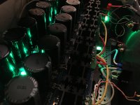
I've been listening to the wild side driving the 2.7QRs by itself for a week or so now, and it's been illuminating. I don't have a preamp yet, so I'm using a cheap USB DAC to drive it. For a lot of music, it's actually a pretty good volume for late night listening. Of course, explaining that this stereo is better than the last one, which lacked a remote control, while this one lacks even a volume knob, is problematic.
It sounds pretty good to me, but it's clearly not anywhere near what it should sound like when I've got all the pieces together (both F4s, Aikido, etc). I expect increasing voltage swing from ~2-3 volts coming from the DAC via the new preamp should help the most.
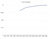
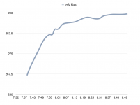
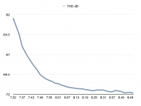
This amp definitely sounds its best after an hour. I was curious how this quantifies, so here are some charts that show what happens over the first hour or so as an F4 warms up. 1 KHz sine wave at 2.83 V across an 8 ohm power resistor. Both channels are being run, but only the right channel is being measured.
It sounds pretty good to me, but it's clearly not anywhere near what it should sound like when I've got all the pieces together (both F4s, Aikido, etc). I expect increasing voltage swing from ~2-3 volts coming from the DAC via the new preamp should help the most.
This amp definitely sounds its best after an hour. I was curious how this quantifies, so here are some charts that show what happens over the first hour or so as an F4 warms up. 1 KHz sine wave at 2.83 V across an 8 ohm power resistor. Both channels are being run, but only the right channel is being measured.
Attachments

- Status
- Not open for further replies.
- Home
- Loudspeakers
- Planars & Exotics
- Happy Ampsgiving 2016! (Magnepan 2.7QR/Aikido/F4)