Sure, I typically do a good deal of EQ on both the send and receive sides at the desk. But I do want to make the output of this unit as clean and usable as possible from the outset.
Slightly off-topic, but I'm trying to repurpose an old reverb tank as a piece of outboard studio gear........It's a reverb circuit. The tank came from a Hammond "tone cabinet" and I'm extrapolating just the reverb-specific parts of the circuit for a standalone unit.
Not sure what kind of tank you have. Hammond made lots of different tanks including several versions of the size typically found in guitar amps.
Back in my teenage years I had several large tanks removed from upright tone cabinets from the 1950's era. These tanks must remain upright since one or more of the springs terminate in a long brass tube which is partially filled with mineral oil to tune the damping of the reflected sound wave. I drove those tanks directly with the output of one of my DIY Fender Champ clones. I had 2 or 3 different versions of these upright tanks wired in parallel on the output of the Champ.
I had a really primitive home studio using 2 reel to reel tape recorders and a DIY mixing console built with germanium transistors salvaged from old radios. I had made several tapes of "music" made with hand spliced tape loops, some guitar and drums, and lots of ambient sounds. I had 3 old Stromberg Carlson vacuum tube (4 X 6L6) power amplifiers, one of which had been modded into a "killer" guitar amp. Sadly, all of this was trashed when I left home under less than ideal circumstances.
A few weeks ago I was wandering the swap meet field at a hamfest in Pennsylvania when I had a flashback from the late 60's.......there it was, an old Stromberg Carlson AU-36B PA amp, just like the ones I had in my late teens. I bought it and plan on recreating that "screamin guitar amp" that I had in the 60's.....I wonder if it will live up to some very old memories......
Now if I could only find one of those old reverb tanks......Ebay to the rescue. I found two old tanks similar to what I had in the 60's, so I bought the cheaper unit. I will do some testing when it arrives to determine the impedance of the drive unit, but it is likely fairly low. Then I plan to create a stand alone reverb unit for use in the modern studio that I am building (PC / DAW based).
If the unit does have an input impedance in the 4 to 16 ohm range, I will probably build a driver circuit using a 6V6 or similar sized tube, and a "Fender Champ replacement" or other small OPT to drive it.
My Champ clones from the late 60's used metal 6L6 tubes, or 6BQ6 TV sweep tubes since I could get both for free. These are two really different tubes, but both can play in the same socket if you have a plate cap connected to pin 3. These are both also possibilities to explore.
Attachments
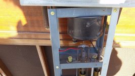
Back in my teenage years I had several large tanks removed from upright tone cabinets from the 1950's era. These tanks must remain upright since one or more of the springs terminate in a long brass tube which is partially filled with mineral oil to tune the damping of the reflected sound wave. I drove those tanks directly with the output of one of my DIY Fender Champ clones. I had 2 or 3 different versions of these upright tanks wired in parallel on the output of the Champ.
Thanks much, this is exactly the sort of reverb tank I'm playing with.
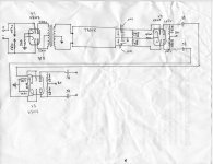
I could say more about the tank itself, but for the moment I'm running into issues with the amp circuit. Using V2 as the output, I was happy with the sound but the output was too low to play nicely with my console (it doesn't seem to return true "line level," and to get usable signal the preamp gain on the return channel has to be cranked up into noisy territory.
I then used V3 as the output stage, but strangely enough this made no difference whatsoever. I'm thinking there may be a couple of issues at play:
1. V2 and V3 are simply biased too low (note the relatively high value of the cathode resistors here).
2. I note that there is no reference to ground for the grids of V3. This seems odd to me; doesn't it typically want one?
3. Is an impedance mismatch going on between the reverb unit and my console? Perhaps if V3 were reconfigured as a cathode follower instead it would play nicer with the console?
Again, V2 in this drawing is incorrect; it's actually 6SC7.
Attachments

Last edited:
Actually I misspoke earlier; there IS a 1 meg reference to ground for the V3 grids, I missed it because in the original Hammond schematic, reverb can be switched out of circuit entirely so it's somewhat hidden....
You state that this circuit won't drive the input of your console. Is the console input a low impedance like 600 ohms? If so that would explain the loss of gain. V2 and V3 are configured for rather high impedance loads. If the console is a low impedance, then making a cathode follower out of V3 would make sense.
That was the only obvious flaw I saw in the circuit.
I will know more about my spring unit once it shows up. I haven't touched one of these since 1972. Back then I had 3 "mixers." The "good one" was a battery operated germanium transistor 6 input mic mixer with the Olson Electronics brand. I worked there at the time. The others were home made units that used 12AX7's. I know that I had the wires from the reverb tank plugged straight into one of the mixers, but it could have been into a low level phono input.
Once this tank shows up I plan on making a stand alone box with one input and several outputs, one output for each tank. I already have 3 different spring tanks that were removed from dead guitar amps, going back to a 1969 vintage Kustom. I will figure out what the tank wants once I have it, but I managed to make it play with the junk I had in the late 60's, so it can't be too hard.
there IS a 1 meg reference
That was the only obvious flaw I saw in the circuit.
I will know more about my spring unit once it shows up. I haven't touched one of these since 1972. Back then I had 3 "mixers." The "good one" was a battery operated germanium transistor 6 input mic mixer with the Olson Electronics brand. I worked there at the time. The others were home made units that used 12AX7's. I know that I had the wires from the reverb tank plugged straight into one of the mixers, but it could have been into a low level phono input.
Once this tank shows up I plan on making a stand alone box with one input and several outputs, one output for each tank. I already have 3 different spring tanks that were removed from dead guitar amps, going back to a 1969 vintage Kustom. I will figure out what the tank wants once I have it, but I managed to make it play with the junk I had in the late 60's, so it can't be too hard.
You state that this circuit won't drive the input of your console. Is the console input a low impedance like 600 ohms? If so that would explain the loss of gain. V2 and V3 are configured for rather high impedance loads. If the console is a low impedance, then making a cathode follower out of V3 would make sense.
I don't actually know the specs of the console's inputs offhand, but inserting into a line input (lo-Z) gives no signal whatsoever, and into a mic input (hi-Z?) gives decent-sounding signal, but at too low a level.
Where I'm currently stuck on V3 is the fact that Hammond configured everything as balanced. I see plenty of examples of circuits using a 6SN7 as cathode-follower output (see attached image) but they typically run the output of one triode's plate into the other triode, and then take a single cathode output.
I'm just inexperienced enough to be thrown by this. Can I simply run caps off both cathodes of V3 in parallel? Or drop one leg of the signal (coming off V2)? Or otherwise sum both signals coming off of V2? Other than that, I'm left with trying to source an appropriate push-pull output transformer for V3, which would not be the end of the world I suppose.
Many thanks!
Attachments

Help Me Understand Cathode Follower
I'm working on an outboard reverb unit for my studio, using an old Hammond reverb tank and based on the circuit that drives and recovers it. I made a crude sketch and attached it here. (Note: V2 is actually 6SC7, and V3 has 1 meg grid resistors, not shown.)
My question is: I'd like to try and build a cathode follower output so the unit will play nicely with the lo-Z inputs on my console. I've looked at a few circuits using 6SN7 cathode follower outputs, but they tend to run one triode into the other. (Also attached.)
Hammond used a balanced layout, so throughout the amp, the "hi" and "low" signals are running in parallel. How would I build a cathode follower with this arrangement? Would I drop one leg? Sum them? Run one follower cap off each cathode of V3? I'd love some ideas, as I'm new at this.
Attachments
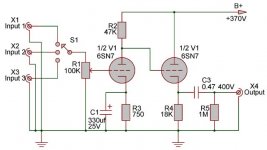
I'd like to try and build a cathode follower output so the unit will play nicely with the lo-Z inputs on my console. I've looked at a few circuits using 6SN7 cathode follower outputs, but they tend to run one triode into the other.
Have you seen this ?
The Valve Wizard -Cathode Follower
 @slor - I merged your two threads... As reminder, it is against the Forum Rules to start multiple threads on the same/similar topic.
Anyway, doesn't a "lo-Z" line input have a higher impedance than the mic input? Which mixer are you using?
Have you seen this ?
The Valve Wizard -Cathode Follower
I totally apologize about double posting jazbo8; I thought it was far enough removed in concept. I'll read the posting rules thoroughly, and be more on the ball.
As for the mixer, it's a Harrison PRO-790. I was referring to the input impedances of the two types of modules, but in retrospect this wasn't helpful (or accurate). What I should have said was that the line modules simply don't play well with the low-level, high-impedance output of the reverb unit as it's currently configured.
And thanks artosalo, I have seen (and often revisit) the Valve Wizard pages! My question is more about using cathode followers in this "balanced" environment, rather than the single-ended arrangement they so often seem to appear in.
I see, but perhaps you can make do without the CF's, if you change V2 to 12AU7 and lower the plate resistors to a much lower value.
I do often see 12AU7s as output drivers in old mixers. Unfortunately I'm a bit constrained by the chassis I'm working with (octal sockets).
I'm guessing this arrangement is simply a bit too esoteric for a "traditional" cathode follower arrangement, so I'm going to source an output transformer and see how that works. My guess is that it will do just fine, though with a higher voltage than specified on the Hammond schematic.
Thanks again!
Forgot... for octal socket, you can always try 6SN7 for V2.
Thanks, I had thought about some substitutions (6SL7 too?).
I'm concerned that there's still the basic issue of impedance mismatch with the console. Still, easy enough to try a swap and see what happens....
The 6SN7 has lower plate resistance than the 6SC7 or 6SL7, so it might just be enough to drive the console's line input.
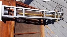
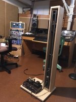
Just wanted to thank folks here again--particularly jazbo8--for the input and advice. Here's a photo of the completed unit ready to be delivered to its new home (no oil in the dampening tubes just yet!).
Unsurprisingly, following the Hammond schematic as much as possible was the best way to go. Used the output transformer included in the amp chassis (found in the trash!) to drive the tank, added a Triad A-65J as output. Sounds great!
Unsurprisingly, following the Hammond schematic as much as possible was the best way to go. Used the output transformer included in the amp chassis (found in the trash!) to drive the tank, added a Triad A-65J as output. Sounds great!
Attachments
Slight update:
After delivering the reverb to its intended owner, we're finding that the console's Aux Send won't drive the reverb sufficiently (console is an API Legacy, I'm trying to get reliable specs on the Aux section).
I'm thinking it might make sense to up the value of the grid resistors on V1 (if memory serves I ended up at 56K). Any other ideas? Perhaps adding cathode bypass caps, or simply lowering cathode resistor values? I don't want to stray too far from Hammond's schematic, as in general I trust they knew what they were doing!
- Status
- Not open for further replies.
- Home
- Live Sound
- Instruments and Amps
- Hammond Reverb - Standalone Unit