You're looking at a 10,000 ohm primary impedance on the output transformer.
Slightly off-topic, but I'm trying to repurpose an old reverb tank as a piece of outboard studio gear. The schematic I'm working off of uses a 6SN7 to drive 6V6s as a power amp, but I'd like to use the 6SN7 in PP as a line amp.
My question is: Would the 10k primary on the output transformer still hold? Reading this thread, I wasn't certain if folks were using a single 6SN7 in PP or a pair with paralleled plates here.
Many thanks!
It should, however depending on the load and gain required you might be better off setting it up as a CCDA.
https://www.tubecad.com/2009/03/blog0161.htm
A quote from the article:
"Just how much gain is needed for a line amplifier? Let's begin the answer with the observation that most line amplifiers have too much gain. Working on the assumption that even the world's most inefficient power amplifier needs only 3 volts of drive signal to be driven to full output and even the weakest tape deck or CD player puts out at least 0.5V of signal, the greatest amount of gain needed would be 6:1 or 15 dB of gain. Yet most tube line stages have between 20 to 30 dB of gain (10:1 to 32:1). While this extra gain impresses the audio neophyte who marvels at the power implicit in the distorted thunder that a mere one quarter twist of the volume knob provokes, it ultimately only subtracts from the useful range of turning on the volume control and usually only worsens the signal-to-noise ratio of the line stage. (Remember, many audio systems don't use any active gain line stage—zero gain—and rely on only passive attenuators and switches to connect line level components to the power amplifier.) If 20 to 30 dB of gain is too much, how much then is best? The answer will depend on each system. (This is the answer most hated by dogmatic audiophiles who seek absolute answers to relative questions...) A safe guess, however, would be 10 to 20 dB of gain, which translates into 3 to 10 times the input signal."
Last edited:
Hey, thanks so much for that! I had considered a cathode follower arrangement, but wasn't quite sure how to implement it. That's good info and guidance.
FWIW, here's my sketch of the circuit as extrapolated from the original Hammond schematic. V2 is mislabeled "6CG7"; it's actually "6SC7." In the original circuit, V3 drivers 4 x 6V6. Perhaps there's even a better choice of output tube than a 6SN7; the chassis I'm building off of has octal sockets installed, and being a novice I'm playing it safe by sticking with the original circuit.
FWIW, here's my sketch of the circuit as extrapolated from the original Hammond schematic. V2 is mislabeled "6CG7"; it's actually "6SC7." In the original circuit, V3 drivers 4 x 6V6. Perhaps there's even a better choice of output tube than a 6SN7; the chassis I'm building off of has octal sockets installed, and being a novice I'm playing it safe by sticking with the original circuit.
Attachments
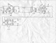
In theory if you want to turn a power amp into a line amp you could just take the output from the driver tubes. V3 in this case. Connect 1M resistors from the 0.33u caps to ground and you have a line amp.
.
.
In theory if you want to turn a power amp into a line amp you could just take the output from the driver tubes. V3 in this case. Connect 1M resistors from the 0.33u caps to ground and you have a line amp.
.
Oh interesting! I'm a bit worried about him from this rickety old arrangement, but it'd certainly be easier to tack it up without a transformer and assess....
An old thread (it's undead), but I'm interested in this question too, so I'll take it up.
Can you post the schematic you have?
I've been confused by 'impedance' specs as they relate to audio transformers and matching this or that load. Basically, the primary impedance specification is only relevant to a particular secondary impedance load. So if your headphones really do present a 600 ohm load, and if you use a transformer specified to be 10k anode-anode primary:600R secondary, then that would probably not be a good choice for a PP 6SN7. That's because the ra (internal anode resistance) of a 6SN7 is going to be somewhere in the vicinity of 10k ohms. For highest power output, you want the primary impedance (resistance?) to be 2X the triode's ra. For better damping/lower distortion, make that 4X the triode's ra (but lower power output).
I think that for a 6SN7, you'd want 40k:600 so that each triode in the pair sees a 20k primary load. Each half of the primary loads one triode, so you want 2X the 6SN7's ra of 10k (valid for class A operation).
If the only OPT you can get is 10k:600, then you'd want to use a tube with much lower ra, perhaps a 5687 or 6N6P run with high anode current of about 15mA each. The ra of a 5687 under those conditions should be 2k to 2.5k, so would be loaded by 5k per triode, or about 2X the triode's ra, which is what you want.
However, these impedances are relative. If you have a 10k:150 transformer, and you use a pair of headphones that present a 600 ohm load on the secondary, that makes the effective impedance of the OPT 40k:600 (600/150 = 4). Fortunately, Edcor makes just such a transformer.
The other problem is primary inductance. When you step up the load on the secondary, the primary impedance rises along with it, but the primary inductance remains the same. That means the inductance presented to the 6SN7 with its higher ra changes the HPF formed by Ipri and Rsource (the ra of the triode). That raises the -3dB down point of the frequency response you'll get from the transformer. If the inductance is pretty low, the F3 of the HPF may be too high for good bass performance.
If what you have is a 10k:600 PP OPT and you must use an octal-base twin-triode, I'd use something like a 6BL7 or 6BX7 rather than a 6SN7, to get the ra low enough to work with the OPT's primary inductance.
If you have a 10k:150 PP OPT, it might work with a 6SN7, as long as the primary inductance is high enough.
I measured the Edcor 10k:150 OPT I have and got a figure of only 15H for the primary with the two halves of the primary in series. Half of that (half of the primary winding) is only 7.5H, That would not work at all for a 6SN7 with ra of from 8k to 10k. The F3 of the HPF formed by ra and Ipri would be 160Hz to 200Hz. No bass. If I plug in 2k as the tube's ra (like from 6N6P with 15mA Ia) I get an F3 of about 40Hz. That would be barely acceptable, but not great.
OPTs have limitations... One way people try to get around all this is to use a bigger PP 3k:16 OPT. The primary inductance of this bigger OPT would presumably be larger than the Lpri of a little 10k:150 line level transformer. Let's say the Lpri of this bigger OPT is 40H. Half of that is 20H. Now if we plug in our 6SN7 ra of 10k we get F3 of 80Hz. Still not there with a 6SN7, but it would work great with a 6N6P or 5687. Even a 6DJ8/ECC88 would work pretty well.
I think I got that right... I encourage you to correct me if I'm wrong.
--
Last edited:
First off, thanks so much for the clear explanation! Jibes completely with my (dim) comprehension of transformer characteristics....
I'm often left to deduction via others' examples. For instance, this offering from Sowter:
PRE AMP OUTPUT TRANSFORMERS
a 15k:600R output transformer. But your point about selecting a higher primary impedance (either nominally or relative to secondary impedance) is well taken.
As for the schematic I'm working off, it's attached. Please note that V2 is actually a 6SC7, not 6CG7 as I wrote. In the "real" amp, V3 feeds 4 x 6V6.
Someone else was kind enough to point out that theoretically, I could just take output off the capacitors coming of the plates V2, first tying them to ground via 1 meg resistors. I'm at least going to try this and see what I get; it's quite possible that's enough output as needed for this unit.
Thanks again!
Attachments

It's not clear what you are trying to do... Are you actually building a reverb circuit or something else?
It's a reverb circuit. The tank came from a Hammond "tone cabinet" and I'm extrapolating just the reverb-specific parts of the circuit for a standalone unit.
So everything is working and you just want to take the output from the recovery stage to your console?
You got it, and thanks! I haven't actually tacked up the recovery stage, but I don't think it will be a big issue. Really just want to make sure output gets back to console with full bandwidth and least hum. With rongon and others' input, I feel like I'm fairly close to resolution!
I see, then taking the outputs from V2 into the board should work (keep the whole chain balanced). BTW, did you ever figure out the spec for the Hammond reverb transformer?
No, I haven't figured that out yet. Someone at the Organ Forum offered to do so (he has a box of them!) but I haven't heard back.
I don't think this is a huge deal; the no-name one I've repurposed from the discarded guitar amp chassis I'm building off of seems to work just fine. Center-tapped, one leg grounded or not, it doesn't appear to much care!
I don't think this is a huge deal; the no-name one I've repurposed from the discarded guitar amp chassis I'm building off of seems to work just fine. Center-tapped, one leg grounded or not, it doesn't appear to much care!
Let's see if the guy gets back to you, would be good to know just for historical purpose, as online search turned up nothing on the spec's for the Hammond and Leslie reverb transformers of that era.
In theory if you want to turn a power amp into a line amp you could just take the output from the driver tubes. V3 in this case. Connect 1M resistors from the 0.33u caps to ground and you have a line amp.
.
Thanks again for this; amp is working well but I'd like to play with frequency filtering. I'm guessing you recommended 1meg resistors at output for full frequency? According to one of those handy calculator sites, a much lower value (around 2.8k) will form a high-pass around 250 Hz, which would be optimal for my purposes here....
2.8k might be too heavy a load for V2, and results in un-wanted distortion. If you want a LPF, it's better to put it in front of the tank.
Right, and thanks for that! Though I was thinking a high-pass as opposed to a low-pass. Really, both would be useful here.
In general I've been trying to alter the signal on the "pre-" side as opposed to the "post." Only place I think I can achieve this is directly on the input, given how little circuitry there is before the tank. With the grid resistor value I settled on (56k), the filter calculator app gives me a capacitor value of roughly .01.
In general I've been trying to alter the signal on the "pre-" side as opposed to the "post." Only place I think I can achieve this is directly on the input, given how little circuitry there is before the tank. With the grid resistor value I settled on (56k), the filter calculator app gives me a capacitor value of roughly .01.
I'm going to! I also realized that reducing the value of the resistor at output would essentially turn the arrangement into a volume control, no? Definitely not trying to attenuate the output; I'm concerned that with filtering, I'm going to have to add back that last gain stage (V3) to have enough for my purposes.
It also occurs to me that I may have to bite the bullet and buy a proper output transformer if I want less low-end noise. I haven't done a "proper" test with my console, but this is a concern.... I'll keep posting with my findings, thanks again for the support!
It also occurs to me that I may have to bite the bullet and buy a proper output transformer if I want less low-end noise. I haven't done a "proper" test with my console, but this is a concern.... I'll keep posting with my findings, thanks again for the support!
- Status
- Not open for further replies.
- Home
- Live Sound
- Instruments and Amps
- Hammond Reverb - Standalone Unit