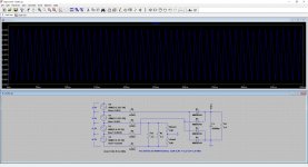
Thanks euro21, I was just doing the same thing, see attached. There's a fair bit of ripple indeed, the voltage doubler looks okay though. I modelled using the actual 378X transformer specifications as found on the Hammond website.
Hammond 378X transformer
https://www.hammfg.com/files/parts/pdf/378X.pdf
Perhaps in the voltage doubler put the filaments in series with small resistor to equalise the current? Less stress on the transformer with using only half the current.
Having said this using in the way you've modelled will result in slow start of the filament. Both solutions have their advantages and disadvantages.
Excellent idea.why Hammond doesn’t just offer a winding on their PTs that is ideally suited for full wave bridge rectification and able to provide heater current for 3-4 small signal tubes, seems like a no-brainer to me? They could just add some extra windings to the existing 6.3V CT, make a 8V CT winding with 6.3V taps for example, so you have the option to do that, those few meters of copper wire would be well worth the cost.
In fact, the 8V winding does not need to be center tapped, since once it becomes DC, "hum bucking" becomes irrelevant.
So they would need to add a few extra turns only to one half.
They could offer: 3.15-CT-3.15-4.85 , all VAC, all relative to CT
Usable with a full bridge rectifier.
@JMFahey,
I could get a little adventurous and hook de 5V CT in series with the 6.3V CT and take the voltage in between the CT, this would yield 3.15+2.5=5.65V? If I then use a silicon bridge rectifier and some series resistors in front of it I should be good to go? Or not? Getting creative with transformer windings always gives me a headache? What would that do to the heaters on the output tubes that are fed AC from the 6.3V CT?
I could get a little adventurous and hook de 5V CT in series with the 6.3V CT and take the voltage in between the CT, this would yield 3.15+2.5=5.65V? If I then use a silicon bridge rectifier and some series resistors in front of it I should be good to go? Or not? Getting creative with transformer windings always gives me a headache? What would that do to the heaters on the output tubes that are fed AC from the 6.3V CT?
Coming up with a 'suits all' solution quickly puts one out of the market. Not everyone drives a RR, Fords & Chevies are a lot less money. And still get us there, for the most part on time!
How’d you know I drive a Ford? 😀
@JMFahey,
I could get a little adventurous and hook de 5V CT in series with the 6.3V CT and take the voltage in between the CT, this would yield 3.15+2.5=5.65V? If I then use a silicon bridge rectifier and some series resistors in front of it I should be good to go? Or not? Getting creative with transformer windings always gives me a headache? What would that do to the heaters on the output tubes that are fed AC from the 6.3V CT?
Actually that looks like it can work? Have a look at the simulation, I just can't GND any part of the 6.3V winding, as that would mean excess currents will flow (which is why the 0.001 resistors are in the simulation, so I can check currents). I can however still use humdinger resistors, just going to need some 10R or so protection resistors at either end of the potmeter so I don't hook either end of the 6.3V CT winding to GND or things get nasty again.
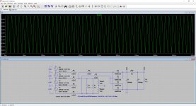
Another option would be the obvious one, and simply full bridge rectify the 6.3V 6A CT winding with a regular ol' silicon bridge. That seems to work well too, I might just need a small series resistor, R10, to bleed off some excess voltage, or simply not worry about it as anywhere between 6.0-7.0V is usually good. Ripple is about 300mVpp, not great, but better than AC. I love having options! 😀
Attachments
Last edited: