Hi!
In advance, Happy New year!!
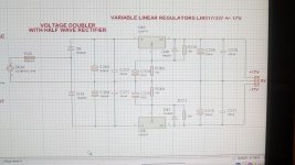
I have designed a dual rail +/-17v voltage doubler psu, with LM317/337 regulators, powered by a 18v AC wall wart transformer.(no center tap).
The fact is that i still have too much ripple: vp-p is 5,7mv. 926uv RMS. for a current draw of aprox 45ma per rail.
I think one way to reduce the ripple is to add a cap in parallel with the rectifier diodes.(snubber) with 10 or 100nf 100v.
Another idea is to add a 10nf x2 cap at the AC input, with one cap leg to gnd. but i'm not sure about this.
Thank you for your advise!
Jay x
In advance, Happy New year!!
I have designed a dual rail +/-17v voltage doubler psu, with LM317/337 regulators, powered by a 18v AC wall wart transformer.(no center tap).
The fact is that i still have too much ripple: vp-p is 5,7mv. 926uv RMS. for a current draw of aprox 45ma per rail.
I think one way to reduce the ripple is to add a cap in parallel with the rectifier diodes.(snubber) with 10 or 100nf 100v.
Another idea is to add a 10nf x2 cap at the AC input, with one cap leg to gnd. but i'm not sure about this.
Thank you for your advise!
Jay x
Last edited:
DO NOT add capacitors between the AC input and ground unless they are class X and class Y respectively. That will have no effect though.
I presume you have one rec for +ve and one for -ve, Ground being the transformer winding that is not connected to the diodes.
Have you used the correct value smoothing capacitors and taken the common to ground where the transformer is connected? That is very important.
A diagramme would be helpful.
Happy New Year. ��
I think one way to reduce the ripple is to add a cap in parallel with the rectifier diodes.(snubber) with 10 or 100nf 100v.
This is certainly not a way to reduce the ripple. You can either up the main smoothing caps, or add an LC/RC section, which is probably impossible.
Why are you unhappy with the amount of ripple?
My suggestion would be to use UF4007 diodes.
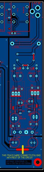
Also the CT to rectifier filter caps connection has high current pulses, so better to restrict that connection to thick traces side by side with the + and - raw supply rails. Use the 0V end of the regulator adjust circuits as the star node to then flood out to everywhere, or even better to take C276/275 terminals back directly to that star node (rather than use the flood). There are many app notes for voltage regs that show the star aspect of that 0V node.
If the transformer secondary has significant leakage inductance, then also aim to use a CRC snubber across the winding as soon as it connects to the pcb - see Mark Johnson's quasimodo threads.
Last edited:
")
Another thing to consider is that you may not have enough voltage 'over head' for the regulators to work?
This is 1/2 wave so, 18 volts ac gives you a dc voltage of 25 volts off load (18 x 1.4 off load peak), but as soon as you draw current that drops to 16.3 volts (18 x 0.9 on load average.)
Just thinking out loud...
Alan
This is 1/2 wave so, 18 volts ac gives you a dc voltage of 25 volts off load (18 x 1.4 off load peak), but as soon as you draw current that drops to 16.3 volts (18 x 0.9 on load average.)
Just thinking out loud...
Alan
Last edited:
Since the wall wart provides 18VAC, you've got plenty of excess voltage at the input of the LM317/LM336 regulator ICs: about 23 V or so. This is convenient; it allows you to drop some voltage across a pre-filter and still meet the regulator chip's minimum input requirement, which is about 21V.
You can split capacitor C263 into two pieces. Instead of one 1000uF capacitor, you can make it two 470uF capacitors with a 27 ohm series resistor between them. Your 45 mA of load current flowing through the 27 ohm resistor, drops only 1.2 volts so you'll still have more than enough voltage at the input to the IC.
BTW I don't think snubbers are relevant to this problem, at all.
Hi!
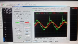
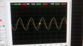
I tested my audio processor, with true RTA software, and a software scope. 1khz sine@775mv aprox, and measured the output.
Here are two pictures.
The one with sines is when Signal is on, at unity gain.
The one with more ripple is without Signal, at Unity gain.
Jay x
I tested my audio processor, with true RTA software, and a software scope. 1khz sine@775mv aprox, and measured the output.
Here are two pictures.
The one with sines is when Signal is on, at unity gain.
The one with more ripple is without Signal, at Unity gain.
Jay x
Attachments
- Status
- This old topic is closed. If you want to reopen this topic, contact a moderator using the "Report Post" button.
- Home
- Amplifiers
- Power Supplies
- Half wave rectifier snubber