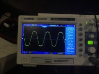
I’ve had this one in my mind for a while and I finally did get a version working
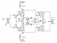
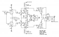
The idea is to directly couple to a triode strapped pair of GU-50s in a push pull output stage.
It’s tricky because GU-50s are quite low gain in triode mode and need almost 200v p-p. This means nearly -100v on the grids.
So the driver needs to have the plates at -95v or so and be able to swing 200v p-p. No small task.
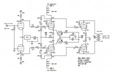
Also the plate V needs to be individually adjustable so I can bias up the GU-50s. This is why I decided to use choke loaded stages on current sources.
I was originally going to use a pair of 6v6 but recent experiments with the 6E5P made my want to try those.
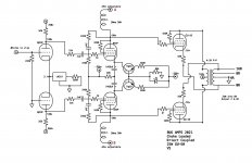
This circuit is functional as drawn but I think I will be adding local FB at the driver and a input gain stage will replace the input transformer.
What do you think?
The idea is to directly couple to a triode strapped pair of GU-50s in a push pull output stage.
It’s tricky because GU-50s are quite low gain in triode mode and need almost 200v p-p. This means nearly -100v on the grids.
So the driver needs to have the plates at -95v or so and be able to swing 200v p-p. No small task.
Also the plate V needs to be individually adjustable so I can bias up the GU-50s. This is why I decided to use choke loaded stages on current sources.
I was originally going to use a pair of 6v6 but recent experiments with the 6E5P made my want to try those.
This circuit is functional as drawn but I think I will be adding local FB at the driver and a input gain stage will replace the input transformer.
What do you think?
Attachments
-
 AB72D525-E486-490E-9AE4-712F7A96D140.jpeg169 KB · Views: 381
 -
 8C406E4B-43E6-41D1-B68E-5AB737C9AFBA.jpg998.3 KB · Views: 382
 -
 F69BB971-0EF0-44C8-806F-B2F6E7CFBEE6.jpeg631.9 KB · Views: 317
 -
 576FB995-36C8-471E-AAB5-E1670DCB8FAA.jpeg640.8 KB · Views: 310
 -
 C41BB726-5466-4C38-BEF5-CFE695856673.jpg602.7 KB · Views: 328
Yeup. A few people on this forum have actually tried the same thing. I have a similar thing planned with a SE 10Y -> 300B amp. It's definitely a neat idea. It's basically a stacked power supply but centered around ground vs stacked on top of ground.
How hare brained can it be, if it works? 😉
You could use the 12AT7 LTP found in "El Cheapo" to replace the step up trafo at the unit's I/P. Because you direct couple between the tubes currently in place, the high stability of the GNFB loop found in "El Cheapo" would be retained, if you want to try it. Having only 1 RC high pass pole in the signal path avoids unwanted fulfillment of the Barkhausen criterion for phase shift oscillation. 😀
You could use the 12AT7 LTP found in "El Cheapo" to replace the step up trafo at the unit's I/P. Because you direct couple between the tubes currently in place, the high stability of the GNFB loop found in "El Cheapo" would be retained, if you want to try it. Having only 1 RC high pass pole in the signal path avoids unwanted fulfillment of the Barkhausen criterion for phase shift oscillation. 😀
Attachments
Yea, I was think I may use a 6n1p but I’ll definitely be using a differential stage at the front for phase split.
It looks like you're running those GU-50 triodes with 514.45V plate-to-cathode. Is that right? All the advice I've seen is to not exceed about 400Vp-k. Do they run well with that high a plate voltage? Thanks.
In my experience yes, I have a previous gu-50 triode strapped amp design that uses 580v across the outputs and it’s been working fine for over a year now.
What you could do as a cheap fix, this is not criticism, far from it. As i am quite impressed by your progress.
You could take a TL783 for the CCS. Put say 4.7K in series with it, and tie it to the negative rail. In that way you can swamp the rollof of the CCS impedance once you hit past 10Khz in frequency. But a DN2540 is accurate enough. If you get them from the same batch, my experience is that a 100R current set resistor will yield 18mA or so.
Also you are starving the 6DJ8 =6N23P somewhat in that configuration. So you will have higher unlinearity and thus some higher order harmonics.
I know you are using SS in the rectification, i would be careful with the 6DJ8's and never put over 200V over them in cold configuration. It could be worthwile to knock off 50V in a RC filter with zeners to ground, once the LTP starts conducting the zeners are pulled out of conduction by the plate current through the RC filter.
You can clamp the LTP to -0.7V with respect to ground with say a BAV21 small signal diode, but that is just splitting hairs.
Cheers,
V4LVE
What is the purpose/benefit of this direct coupling?
And, what class will the power stage be running?
And, what class will the power stage be running?
That is a hard question to answer, For LF amplification: id say the benefits are only marginal. But as an engineering exercise these amplifiers are better because they remove blocking distortion inherent in PP output stages.
From the schematic you can see that there is 0.55V over the GU50 10R measurement resistor. so its likely a class AB amplifier stage biased at 55mA current. At 500V loaded B+ this works out at 25.5W plate dissipation give or take.
If you really want to see what a high performance direct coupled amplifier looks like: look at the schematics on something like a tektronix 585 oscilloscope Y amplifier. You will see a boatload of trim potentiometers and trimmers to trim the frequency response and DC offset for the amplifier. If you turn one of these on it will take up to 30 minutes before the trace stops drifting across the screen but once its all warmed up and the tubes and supplies are stabilized they are rock solid machines. And a pleasure to work with. you can mess up bigtime and touch 1KV with a 1:1 DC probe and nothing interesting happens.
Prople gut these dinosaurs of tube technology nowadays so they can use the 6DJ8 in some poorly designed Chinese headphone amplifiers. Modern tube audio cannot hold a candle to the engineering that went into making a oscilloscope like that. And there are STILL applications where these scopes beat prettymuch everything when it comes to being immune to monkey mistakes( see above)
Cheers V4lve.
What you could do as a cheap fix, this is not criticism, far from it. As i am quite impressed by your progress.
You could take a TL783 for the CCS. Put say 4.7K in series with it, and tie it to the negative rail. In that way you can swamp the rollof of the CCS impedance once you hit past 10Khz in frequency. But a DN2540 is accurate enough. If you get them from the same batch, my experience is that a 100R current set resistor will yield 18mA or so.
Also you are starving the 6DJ8 =6N23P somewhat in that configuration. So you will have higher unlinearity and thus some higher order harmonics.
I know you are using SS in the rectification, i would be careful with the 6DJ8's and never put over 200V over them in cold configuration. It could be worthwile to knock off 50V in a RC filter with zeners to ground, once the LTP starts conducting the zeners are pulled out of conduction by the plate current through the RC filter.
You can clamp the LTP to -0.7V with respect to ground with say a BAV21 small signal diode, but that is just splitting hairs.
Cheers,
V4LVE
I’m definitely starving the 6n23p I need to optimize it’s OP. I may need to put the CCS negative or the grid positive a bit to keep it dropping out at normal OP. My B+ has a large time constant and so the input tube has a hot cathode by the time it sees Hv.
I’m not worried about the dynamic resistance of the CCS in the second stage, it’s got a 10R AC ground path anyway.
I may be considering other input tubes. I have many on hand to try. However when I trace distortion through the circuit 90% of it originates in the final power stage.
Thanks for all your suggestions it’s really helpful to think through them.
What is the purpose/benefit of this direct coupling?
And, what class will the power stage be running?
Direct coupling is helpful here because there is not cap to charge negative when the grid swings positive of the cathode. This preserves the OP of the output tubes in overload. This is known as blocking and leads to nasty crossover distortion.
This is definitely a class AB circuit.
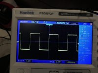
Cleaned up some distortion and lowered the output Z
I need to sort out the input stage still but I’ve got the output stage behaving better now with the use of some cathode FB. Output Z is down to a reasonable 4.3R on the 8R tap.
I need to sort out the input stage still but I’ve got the output stage behaving better now with the use of some cathode FB. Output Z is down to a reasonable 4.3R on the 8R tap.
Attachments
This is definitely a class AB circuit.
I was implicitly asking whether AB1 or AB2 in relation to the need for direct coupling. Your last post answered that.
I’m sorry I misunderstood you.
It swings a bit into positive grid territory but I wouldn’t say it’s full AB2
It swings a bit into positive grid territory but I wouldn’t say it’s full AB2
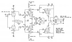
Circuit V7
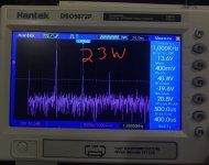
Lots of progress on the circuit. I’m starting to listen to it now too. Just one channel on the bench but it’s a start.
The B+ went up to accommodate a available Antek PT. That’s just as well because now it’s making about 35w and that’s what The output transformers are rated at anyway.
Lots of progress on the circuit. I’m starting to listen to it now too. Just one channel on the bench but it’s a start.
The B+ went up to accommodate a available Antek PT. That’s just as well because now it’s making about 35w and that’s what The output transformers are rated at anyway.
Attachments
Power transformers, Chassis and more local FB
So I've ordered a chassis. It's one I've used on a previous build.
Pesante 4U – diyAudio Store
A also chose some power transformers from AnTek. That made me adjust my circuit voltages to more closely represent those I'll actuality be generating.
I went with a 200w 230-0-230, that will run the 560v and 280v rails. The GU-50s will idle at 40-50ma each but as this amp is very A/B they will draw around 100ma each at full power.
For the -320v rail I ordered a 100w 275v. The 6E5Ps draw 20ma each so the transformer is a bit overkill.
Apart from the circuit changes regarding voltage I've also tweaked the plate FB around the 6E5P to get the gain closer to what I want. I've also adjusted the size of the FB cap. I've actually sized it such that iy provides a slight bass boost shelf. I had a bit of roll off due to the output transformer and this pretty closely corrects it.
I also waned to further reduce the little distortion that was left in the output stage so I added a few DB of plate FB there. To load this FB I needed to add series resistance to the driver. This basically limits the amp to AB1. I don't mind this as the circuit is still making close to what the output transformers can handle.
I'll be drawing up a comprehensive PS circuit soon.
Next step is designing the PCBs! =)
Attachments
does it sound ( or spec ) any better then if you used a standard B+ driver setup and coupling caps to the output stage ?
does it sound ( or spec ) any better then if you used a standard B+ driver setup and coupling caps to the output stage ?
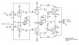
Unsure, I have a previous GU-50 design that resulted in a amp that I love and still use. It's a more traditional circuit like you described.
This new design is just fun for me because its different and interesting. I'll have to wait until it's finished and in system to see if I prefer it.
Comparing measurements like FR, power and output Z will be easy enough. I've attached the circuit from my previous effort.
Attachments
Anode Choke
You can use one of this: Anodendrosseln
I like 62.16G. It is good up to 20mA.
my project: 6C4C in PP (Loftin White)
You can use one of this: Anodendrosseln
I like 62.16G. It is good up to 20mA.
my project: 6C4C in PP (Loftin White)
- Home
- Amplifiers
- Tubes / Valves
- Hair brain direct coupled choke loaded driver stage on a large negative rail.