I'm building a pair of monoblocks using my trashed DH-220
and DH-200 and MC's Signature cards. I installed MC's GX
mods in the late 80s in these amps, but only 1 of the 4
total channels work(ed).
My electronics knowledge is fair to poor, so I have some
questions and thought I'd briefly share the project's
progress. (I'm a smidge better at fabrication than electronics)
So far I've completed the power supply section
in one block. A few photos. ...
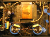
This is the filthy GX modded 220 before major surgery.
I'm retaining the stock xfmr, mosfets, sinks, chassis, and
LC-200 filter caps I installed a few years ago.
and DH-200 and MC's Signature cards. I installed MC's GX
mods in the late 80s in these amps, but only 1 of the 4
total channels work(ed).
My electronics knowledge is fair to poor, so I have some
questions and thought I'd briefly share the project's
progress. (I'm a smidge better at fabrication than electronics)
So far I've completed the power supply section
in one block. A few photos. ...
This is the filthy GX modded 220 before major surgery.
I'm retaining the stock xfmr, mosfets, sinks, chassis, and
LC-200 filter caps I installed a few years ago.
Attachments
Here the amp has been gutted, cleaned, and new wiring and components installed.
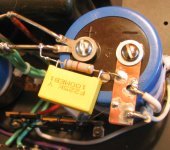
Those are Ixys, 12 amp, 600 piv diodes. No heatsinks.
I decided to make small copper buses to make sure the bypass caps and resistor will fit under the cover. It is possible using multiple regular lugs, but I thought this was a better approach.
I thought about using toroid power xfmrs; but reading this forum convinced me to stay with the stock units.
I may replace the stock binding posts and install a soft start circuit.
The V - shaped addition to the star ground wire, connected to the CT, is specified by Musical Concepts. Something about isolating Charging gradients. I'll have to study up on that one.
Attachments

Just a close up. I spent a lot of time coming up this
and there's probably a better way. I'm trying to
minimize potential oscillation problems, though
such concerns may be unwarranted.
The heavy internal wiring is 16# Carol (supplied with kit)
and 16# pulled from a Lowes extension cord. I thought
of using heavier, but think -- hope -- this wire is ok.
That's the extent of my work thus far. Now I must
tend to installing the new PCBs, new (used) Mosfets,
then final assembly. I have a variac, scope, and sig
generator.
I'm not crazy about the condition of the old mosfet
sockets: some warping and HS compound pollution. I can
Probably fix them but wonder if I should replace
or solder wires directly to the pins?
I assume fresh Radio Shack heat sink compound is
sufficient?
That's it for now. Thanks for looking. I've been reading
DIY for years.
Wink
Attachments
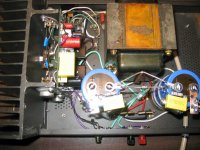
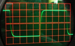
Finished
The first monoblock finished. It seems to be working fine. Biased at 330 ma. I can't really tell how it sounds yet -- only one channel and not broken in. John Hillig says break-in takes about a month.
I am a bit concerned about the square wave performance.
The first monoblock finished. It seems to be working fine. Biased at 330 ma. I can't really tell how it sounds yet -- only one channel and not broken in. John Hillig says break-in takes about a month.
I am a bit concerned about the square wave performance.
Attachments

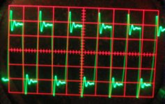
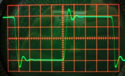
Square wave, 2.2 ufd added
The result with a 2.2 ufd paralled with the 8 ohm load.
Not sure what to make of it. Overshoot and ringing
obviously.
I'm reading this threads such as:
"Square wave testing....Cap value" and others in an
effort to learn proper test methods.
The result with a 2.2 ufd paralled with the 8 ohm load.
Not sure what to make of it. Overshoot and ringing
obviously.
I'm reading this threads such as:
"Square wave testing....Cap value" and others in an
effort to learn proper test methods.
Attachments
The scope is an old tube Tektronics RM-15 (rack mount 515, 15 mHz) I found NOS at an Army surplus store, and function generator a Tenma 72-380.
I did look at the output of the Tenma directly connected to the scope and it looks perfect.
Now on to building #2 monoblock!
I did look at the output of the Tenma directly connected to the scope and it looks perfect.
Now on to building #2 monoblock!
Re: Square wave, 2.2 ufd added
At first sight it looks acceptable but the scope you use may not reveal everything because of its apparent limited resolution. You do not need to show several cycles. Only one is sufficient and it would incease the size of the trace...
However, the stock DH-200/220 has normally a very good response with that load (ringing is not very high and is damped quickly)....
Also ,when you do the test ensure to have short cable from amp to the load and good connection too...
Wink said:The result with a 2.2 ufd paralled with the 8 ohm load.
Not sure what to make of it. Overshoot and ringing
obviously.
I'm reading this threads such as:
"Square wave testing....Cap value" and others in an
effort to learn proper test methods.
At first sight it looks acceptable but the scope you use may not reveal everything because of its apparent limited resolution. You do not need to show several cycles. Only one is sufficient and it would incease the size of the trace...
However, the stock DH-200/220 has normally a very good response with that load (ringing is not very high and is damped quickly)....
Also ,when you do the test ensure to have short cable from amp to the load and good connection too...
Re: Re: Square wave, 2.2 ufd added
Fab,
This scope has magnification capability, pix of which I didn't think to include. I will post much higher rez photos tomorrow.
The load is inserted directly into the amps binding posts and cable to scope is ~ 2' long. My "resistive" load is a bunch of paralleled 1/2 w, 10 ohm carbon resistors.
Regarding stock 220/200s -- of course the Musical Concepts pa-3d card is a vast departure from the original PC-19 driver card.
I've been looking at square wave tests of highly regarded tube amps at Stereophile's site. Interesting.
Thanks for your response.
Wink
fab said:
At first sight it looks acceptable but the scope you use may not reveal everything because of its apparent limited resolution. You do not need to show several cycles. Only one is sufficient and it would incease the size of the trace...
However, the stock DH-200/220 has normally a very good response with that load (ringing is not very high and is damped quickly)....
Also ,when you do the test ensure to have short cable from amp to the load and good connection too...
Fab,
This scope has magnification capability, pix of which I didn't think to include. I will post much higher rez photos tomorrow.
The load is inserted directly into the amps binding posts and cable to scope is ~ 2' long. My "resistive" load is a bunch of paralleled 1/2 w, 10 ohm carbon resistors.
Regarding stock 220/200s -- of course the Musical Concepts pa-3d card is a vast departure from the original PC-19 driver card.
I've been looking at square wave tests of highly regarded tube amps at Stereophile's site. Interesting.
Thanks for your response.
Wink
Hi wink,
I'm seriously concerned about your resistive load. You mentioned on one hand an 8 Ohm load but in your last post I could read on the other hand you paralleled a "bunch" of 10 Ohm(!) resistors.
Well, if you parallel just two of them it would result in 5 Ohm, 4 of them in 2.5 Ohm, etc.
Be honest - how many have you really paralleled?
My advice would be to get somewhere resistors with a (much) higher power rating and a value that can be paralleled with much more ease to reach values like 4 and/or 8 Ohm. I'm for instance using 39 Ohm 10 Watt resistors and parallel 10 of them. Inclusively all soldering joints, cable and contact resistance I come up with a value very close to 4 Ohm. A more precise value would be 9x 39 Ohm + 1x 47 Ohm = 3.97 Ohm. The missing 30 Milliohm will be better accomplished by cable/connector resistance than in my case where round about 100 Milliohm needs to be added. But - what the heck - a little "overload" won't hurt that much 😉
Egad...
Corax,
That should be 100 ohm resistors, not 10. But I just measured the resistance of the bunch again and am getting 10 ohms! Believe it or not, I know the formula for calculating parallel resistance. I think....
Rt = 1/(1/R1 + 1/R2 ...1/Rn), or X = R/Rt, for same value resistors where X is the number, R = resistor value, and Rt = desired resultant.
So I heavily soldered 13 in parallel and measure 7.5 ohms. This was intended for small signal testing only. I actually used a 10 ohm, 10 W wirewound initially and the results are not much different. In fact, the no load trace isn't much different than that produced with resistive loading, wirewound or carbon. Adding capacitance otoh .... ouch, I think.
Starting over on this one. I like your method -- Thanks.
Wink
Hi Wink
I do not see any problem with your latest set of scope traces. It is absolutely normal to have this kind of waveform upon "uf" range of capacitive loading. Even this one is good. If you have a "stock" Musical concept board what are you trying to discover? It should behave as designed....
Thanks
I do not see any problem with your latest set of scope traces. It is absolutely normal to have this kind of waveform upon "uf" range of capacitive loading. Even this one is good. If you have a "stock" Musical concept board what are you trying to discover? It should behave as designed....
Thanks
fab said:Hi Wink
I do not see any problem with your latest set of scope traces. It is absolutely normal to have this kind of waveform upon "uf" range of capacitive loading. Even this one is good. If you have a "stock" Musical concept board what are you trying to discover? It should behave as designed....
Thanks
What am I trying to discover? Well, I was curious to have a look at the PA-3D Signature's behavior; but more importantly, I want to make sure my installation is behaving properly.
Remember that I'm making monoblocks which changes things somewhat compared to a typical MC mod of a Stereo 200 or 220. For example, there are no more fuse blocks bolted to the chassis bottom -- the fuses are onboard the pa-3d board. This requires different wiring runs, but ones that are actually much more direct and shorter in many cases. So the odds of oscillation or some other beastie are probably less.
Something else is I wanted to make sure I didn't kill a power mosfet with esd, although I think such death would have shown up during initial power up.
Overall, I'm just making sure the finished product is working ok.
Wink
Wink said:
What am I trying to discover? Well, I was curious to have a look at the PA-3D Signature's behavior; but more importantly, I want to make sure my installation is behaving properly.
....
Something else is I wanted to make sure I didn't kill a power mosfet with esd, although I think such death would have shown up during initial power up.
Overall, I'm just making sure the finished product is working ok.
Wink
Ok I see.
By the way if you had one dead mosfet it would show on the scope traces...and the ones you have shown are correct.
Thanks

- Status
- Not open for further replies.
- Home
- Amplifiers
- Solid State
- Hafler/MC PA-3D M-block project