Hey all.
Just picked up a DH-500 in unmodded and very nice condition. Everything works, and it sounds pretty good. I don't think it was used much, and looks like a factory assembly in 1983.
I think I have read about every DH-500/DH-200 thread on this board, and am proceeding with some simple mods. (BTW - This board is fantastic!)
So far I have replaced the input RCAs with better quality and have run two-wire shielded cable to the amp boards from the RCAs. I have also replaced the original speaker connectors with Cardas.
I plan to replace the circuit board electrolytics, and by-pass the filter caps. I thought about putting a CL-60 thermistor in series with the incoming AC and bypass that with a 48v relay, but see that the DH500 has an inrush limiter circuit. Is that sufficient?
I discuss the filter caps below, but is there anything else you all would recommend doing?
Other Questions:
Question 1: DC offset level at the left and right speaker outputs measures about 4 mv and 55 mv, respectively, at idle. These seem like acceptable levels, but is the difference significant?
Question 2: I measure the rail voltage off the filter caps at 94 volts under load (95 at idle). This seems a little high, since it supposedly should be approximately 90 volts. Should I be concerned? How is voltage regulated in this thing? Zener diode? (I measure about 140 volts AC at the transformer secondary connections to the diode bridge)
Question 3 (last one): I measure ripple voltage at the main PSU filter caps of about 50 mv at idle, and varying upwards of 200 mv under load. Again, should I be concerned, or is this reasonable? Would I do better by putting in new and bigger filter caps?
Thanks for any and all help!
Peter
Welcome to the hornets nest Peter,
DC offset as a rule of thumb anything less than 100mv is acceptable with 0.000 being desirable. Your DH500 should have the PC19 driver boards with 2 trimpots P1 and P2(manual and schematics are downloadable from Hafler.com/techsupport). P1 is near the top of the board near the signal input, this is your dc offset adjustment.
Replace all the electrolytics as they are ancient. Modern electrolytics are smaller as a rule. There is a lot of discussion on the Hafler DH200/220 mod thread about this. Concensus seems to be C5- is a non polar 470uf/10v,C8 and C10 can be replaced with 220uf/100v low esr caps. As for the filter caps bigger is better and a new bridge rectifier is cheap insurance.
Lots of good info on the other hafler thread start at page 1.
Elwood
Thanks, Elwood...
Yeah, I saw that 200/220 thread, but ended up a little confused as to what the consensus views are. Your response helped.
I think I will replace the old 20,000 uf filter caps as well, probably with some Chemicons.
So, do you think the ripple AC voltage I can measure off these caps is in an acceptable range?
Pete
good evening, Pete
there are several good discussions on p/s design etc.,
go to www.passlabs.com/articles to start and there is a
thread devoted to p/s stuff. You can always do a search on the
forum for specific issues as well..
Elwood
there are several good discussions on p/s design etc.,
go to www.passlabs.com/articles to start and there is a
thread devoted to p/s stuff. You can always do a search on the
forum for specific issues as well..
Elwood
mtflycaster said:...So, do you think the ripple AC voltage I can measure off these caps is in an acceptable range?
Pete
Yes they are.
Progress on the DH-500...?
Slow.
I did manage to replace a couple of caps on the boards, the bipolar ones, with 470uf Nichicons BPs. I hope to get all the others done this week, including substituting 220uf/100v panasonic FCs for the original 100uf/100v ones.
Also, for additional inrush current protection before the power switch, I put two CL-60 thermistors in series across a 48vdc SPST relay, and hooked the relay into the existing relay driver circuit. Of course, the voltage dropped, so had to replace the 1500 ohm 2 watt resistor on the driver board with a 220 ohm 3 watt resistor to get the voltage back up to about 48vdc. The resistor in question is "R120" in the Hafler manual.
This thing actually works! It takes about three seconds after switching the amp on for the thermistors to get hot and the relay to kick on and bypass the them. Since I also plan to increase the psu capacitance by about double (4x22,000uf) I thought this would be helpful. Maybe protect the diode bridge, too?
Questions...
- I remain baffled by the debate over whether the psu caps should be bypassed. I'm going to put in U36D Chemi-cons. Anyone have any definitive experience with these? If so, how?
- With 4 2.5 inch diameter psu caps, I need to relocate the fuse busses. Should I be concerned about staying as far away as possible from sources of AC and also the fan motor? Creative ideas?
Thanks! More later.
Pete
More progress...
I finished putting in the new electrolytics, including only 2 39000uf/100v filter caps rather than 4 22000 as I had considered. What is interesting is that as a result of ONLY do this, the DC offset at the speaker outputs was cut in half (from about 15 to 7mv on ch A and from about 50 to 25mv on channel b).
For me this was unexpected. Why would this be? Tired filter caps Ior caps on the boards, or both, I suppose, but more so an issue with tired/bad board caps?
Next, I further adjusted DC offset using the pots and got it down easily to about zero mv on each channel, though it fluctuates up and down + and - about 4 mv. I'm feeling pretty good. I assume the fluctuations are normal. I played the amp using cheap speakers and it plays fine.
Question: I want to rewire the B+, B- and ground leads from the filter caps to the boards. I am also going to remove the fuses on the chassis floor and substitute and mount tandem fuses up on vertical aluminum strips adjacent to the fan. Anyone see any problems with this??
Here is the question...
Is it preferable to continue to run the power leads from the filter caps directly down to the chassis floor, along the floor, then up to the fuses/boards (as in the unmodded situation) OR to bridge directly across the airspace from the tops of the filter caps to the fuses? Bridging directly would need only about 1/4 as much wire.
Thoughts? Issues? About any of this?
Thanks!!... and more later.
PJ
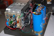
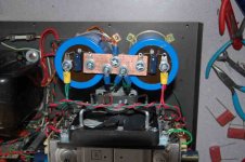
Here is a pic....
Got the fuses moved and used the existing Hafler wire to "prototype" the wiring. No more fuses on the floor of the amp, leaving open the opportunity in the future to add two more big caps.
I intend to rewire with one gauge heavier teflon coated wire, but this looks pretty clean to me. In addition, a portion of the wire run from the big caps to the amp boards will run along the inside of the cover when it is on.
Big caps bypassed only with a 47uF/100v electrolytic, but I plan to bypass the B+ and B- right at the boards with 1uf polys.
Comments? Issues?
Thanks!
Attachments
- Status
- Not open for further replies.
- Home
- Amplifiers
- Solid State
- Hafler DH-500 Questions