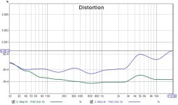
Ok so I had nichicon gold (100uF/25V) in the front end power supply and across the bias curcuit I returned to the capacitors which Rick's documentation suggested. Since they measure better ESR, Vloss, capacitance, ripple current and temperature rating (105°C)
I am able to measure quite low thd values so here are the results.
I am happy to now start on the output stage build and testing.
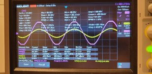
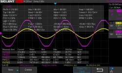
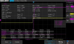
DH500C AFE running on 92Vdc rails. Bias trimmed to match Bob Cordell's design values. Lower curve is measurement system upper curve is DH500C front end.
I am able to measure quite low thd values so here are the results.
I am happy to now start on the output stage build and testing.
DH500C AFE running on 92Vdc rails. Bias trimmed to match Bob Cordell's design values. Lower curve is measurement system upper curve is DH500C front end.
Attachments
Looking good Dan.
I'm also into high voltage ( + / - 84 V) and I will use 3 pairs of exicon's TO264 double die....maybe I can have S version....
Do you thinking at the same?
Did you change R1/R2 to 3k6/3W? How is thermal on those?....also on your heathsinks?
Thx.
I'm also into high voltage ( + / - 84 V) and I will use 3 pairs of exicon's TO264 double die....maybe I can have S version....
Do you thinking at the same?
Did you change R1/R2 to 3k6/3W? How is thermal on those?....also on your heathsinks?
Thx.
Yes, I have the dual die exicon "s" types. Very close to testing time.
I am using a test heatsink.
The 3k6 run hot but you can tough them for 0.2 seconds 🙂
I am using a test heatsink.
The 3k6 run hot but you can tough them for 0.2 seconds 🙂
I think those 3k6/3W will be a problem in a long term....They only lower the U to feed the DC servo OPA2134 with +/- 15V.....and ....common base at Q8/Q14--Q11/Q15.
I'm thinking to came up with an external supply for this and eliminate the "heater". Also a reliable small DC/DC convertor (90V to 15V) should be fine.
What do you think?
I'm thinking to came up with an external supply for this and eliminate the "heater". Also a reliable small DC/DC convertor (90V to 15V) should be fine.
What do you think?
Last edited:
3k6 seems too large.
Bob used 1.5k for the DH200.
The DH 200 no load rails are 63 VDC 63-15 =48 VDC on R1/ R2
48VDC\1.5k = 32ma P=VI = 48 x .032 = 1.5 watts
For the DH 500
Rails are 93VDC at no load.
93-15 VDC = 78 VDC R = V/I = 78/.032 = 2437 = 2.4k
P = 78 x .032 = 2.4 watts
A 5 watt 2.4 k held off the board by an inch seems about right.
The 2134 draws 4ma per channel iQ = 8 ma plus max correction current 15/47000 = 0.3ma x 2 = 0.6ma So 8.6 ma total for the opamp, and base current for the cascodes so 10 ma max. Is the 22ma left for the zener a little high? Why do I feel like Bob will correct me for missing something I should know.
3K6 is my number, not Bob's, I know it works, +/-15V measures around 14.7V with a 90V supply but it could be a bit lower, 3k3, 2k7 should work too. 2K4 well now the zener has to work harder.
How long is that? A DC-DC would be a lot more expense, noisier, and a lot less reliable, but to each there own.I think those 3k6/3W will be a problem in a long term.
Looks good Daniel,
I have designed a few OPS pcbs for this DH-220C design.
In anticipation of a layout like you show, (pcbs mounted on the same plane or HS surface) I did a mirror image pcb layout of the DH-220C OPS called it DH-220CR(OPS) or something like that. I have yet to do the same for the 3 pair OPS as you show. So one would be able to have the connectors face each other and wires could go straight across instead of crossing or doing what you show in your layout.
As a note to above, I have the proto DH-200C running as my lab amp. I measured the V drop across R1 and R2 on one of the AFE's , it measures ~43V across R1 and R2, so with a 1500 ohm I have 28.67mA. This lab proto amp has been powered on continually for about a year now.
Good luck with your OPS power up Daniel
That's cool, I envisioned that setup could be done with some finesse.
I am glad to see you made good use of the extra holes 🙂
Its the mechanical bits that add the extra fun and challenge to the builds and design.
Cheers
Rick
I am glad to see you made good use of the extra holes 🙂
Its the mechanical bits that add the extra fun and challenge to the builds and design.
Cheers
Rick
Last edited:
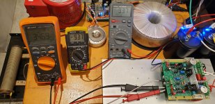
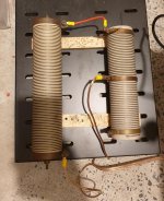
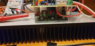
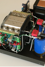
I had to use a soft start since the Variac was complaining about life...
Then I realised the mains to my bench was also sagging under load...
(1kVA toroidal transformer for the DH500C)
I might need to test closer to a power outlet......
-Dan
Then I realised the mains to my bench was also sagging under load...
(1kVA toroidal transformer for the DH500C)
I might need to test closer to a power outlet......
-Dan
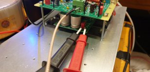
Thanks Felixx,
I am running 400 mA bias (idle is approx 100W)
Heatsink is approx 350 mm x 150 mm x 50 mm
-Dan
- Dan
I am running 400 mA bias (idle is approx 100W)
Heatsink is approx 350 mm x 150 mm x 50 mm
-Dan
- Dan
Hi Felixx,
I haven't listened yet but will soon.
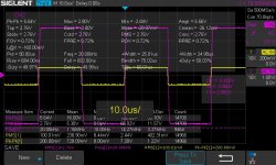
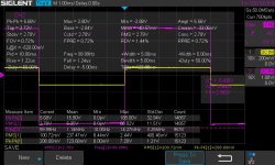
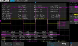
Here are a few more measurements of the DH500C running into 8 Ohms.
Square wave performance is clean, clipping is symmetrical and under control.
The line voltage was slightly higher this time so I had almost 500W into 8 Ohm at clipping.
- Dan
I haven't listened yet but will soon.
Here are a few more measurements of the DH500C running into 8 Ohms.
Square wave performance is clean, clipping is symmetrical and under control.
The line voltage was slightly higher this time so I had almost 500W into 8 Ohm at clipping.
- Dan
Attachments

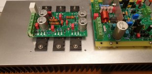
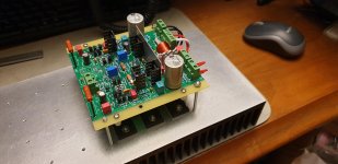
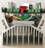
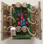
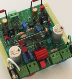
I was involved with the original beta testing for applying the DH220C boards in the DH500 amp (with the help and guidance along the way from Rick). The boards have been operating successfully in my DH500 for about 4 months now so I guess you can consider the application reliable and proven. Below I have included a few pics of the build. I understand Rick will be rolling out the build guide and BOM soon.
I’m very pleased with the sonic improvements. I was going from PC19 boards which had been modified/optimized with premium components and Pooging. Compared to them, the DH-220C boards sound so much better. I immediately noticed the sound stage was much larger and the music more open. Bass is solid, more dynamic with authority. The highs are crystal clear without any harshness. It's like a vail was lifted from the music. The amp really shines with nicer recordings. I can listen to the music for long periods without fatigue. Complex passages remain clean. The performance improvements are due in large part to the advanced circuit design of the DH220C boards (credit to Bob and Rick) plus other changes made which included removing the input coupling caps, bypassing speaker output fuses, using 14 awg coils, and running slightly higher bias. I felt comfortable removing the input coupling caps with the DC servo control on the DH220C AFE boards along with the DC offset protection with the existing DH500 output relay.
With the help of Rick and input from Bob, the following component changes were made to handle the higher 90v DC rail voltages for the DH500. The details will be included in the BOM.
DH220C AFE Boards:
• R1/R2 – Increased the value from 1,500 to 3,300 ohm
• R50 – Increased wattage from 3 to 5 watts
• R51 – Increased wattage from 3 to 5 watts (I actually used two 3 watt resistors in parallel since wasn’t able to find 5 watt rating in the appropriate value).
• C21/C22 – Changed from Nichocon UPJ 470uf/80v to UBY 680uf/100v
• Q20/Q21 Heat Sink – In addition to TO-126 heat sinks, added a thin aluminum plate spanning the two as can be seen in the pics below to hand the added heat dissipation.
• L1 Coil – For the higher power output, increase wire gauge to min. 16 awg. I used 14 awg.
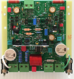
DH500C OPS Boards:
• R4/R5/R8 – Increased wattage from 3 to 5 watts
• R12 – Increased wirewound resistor from 3 to 5 watts. As shown in one of the pics below, had to angle the resistor due to the limited vertical clearance.
• C2/C3/C11/C12 – Changed from Nichicon UVY 220uf/100v to UBY 270uf/100v.
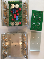
Initially I was going to use the P230 OPS boards but determined they were too wide and would not fit between the heat sink ears and MOSFET sockets. Rick designed a new OPS board specific for the DH500 plus optimized the layout of the board to fit the larger 270uf caps. I chose to tap new holes in the heat sink to securely mount the OPS boards due to the close clearances (instead of letting the boards float being held in place only by the connecting wires like in the DH220). Also used electrical fish tape underneath the OPS board as an added guard against any chance of a short against the heat sink.
I’m very pleased with the sonic improvements. I was going from PC19 boards which had been modified/optimized with premium components and Pooging. Compared to them, the DH-220C boards sound so much better. I immediately noticed the sound stage was much larger and the music more open. Bass is solid, more dynamic with authority. The highs are crystal clear without any harshness. It's like a vail was lifted from the music. The amp really shines with nicer recordings. I can listen to the music for long periods without fatigue. Complex passages remain clean. The performance improvements are due in large part to the advanced circuit design of the DH220C boards (credit to Bob and Rick) plus other changes made which included removing the input coupling caps, bypassing speaker output fuses, using 14 awg coils, and running slightly higher bias. I felt comfortable removing the input coupling caps with the DC servo control on the DH220C AFE boards along with the DC offset protection with the existing DH500 output relay.
With the help of Rick and input from Bob, the following component changes were made to handle the higher 90v DC rail voltages for the DH500. The details will be included in the BOM.
DH220C AFE Boards:
• R1/R2 – Increased the value from 1,500 to 3,300 ohm
• R50 – Increased wattage from 3 to 5 watts
• R51 – Increased wattage from 3 to 5 watts (I actually used two 3 watt resistors in parallel since wasn’t able to find 5 watt rating in the appropriate value).
• C21/C22 – Changed from Nichocon UPJ 470uf/80v to UBY 680uf/100v
• Q20/Q21 Heat Sink – In addition to TO-126 heat sinks, added a thin aluminum plate spanning the two as can be seen in the pics below to hand the added heat dissipation.
• L1 Coil – For the higher power output, increase wire gauge to min. 16 awg. I used 14 awg.
DH500C OPS Boards:
• R4/R5/R8 – Increased wattage from 3 to 5 watts
• R12 – Increased wirewound resistor from 3 to 5 watts. As shown in one of the pics below, had to angle the resistor due to the limited vertical clearance.
• C2/C3/C11/C12 – Changed from Nichicon UVY 220uf/100v to UBY 270uf/100v.
Initially I was going to use the P230 OPS boards but determined they were too wide and would not fit between the heat sink ears and MOSFET sockets. Rick designed a new OPS board specific for the DH500 plus optimized the layout of the board to fit the larger 270uf caps. I chose to tap new holes in the heat sink to securely mount the OPS boards due to the close clearances (instead of letting the boards float being held in place only by the connecting wires like in the DH220). Also used electrical fish tape underneath the OPS board as an added guard against any chance of a short against the heat sink.
Attachments
- Home
- Amplifiers
- Solid State
- Hafler DH-500/P500 Mods