There has been so much ink spilled over the years about the DH-200 / DH-220 amplifier.
And I've had one for years - more or less stock and while it's always been a decent amplifier it's definitely showing its age.
I know that there are plenty of upgrades out there. Musical Concepts mods have been around forever but they're expensive. https://www.musicaldesign.com/Haf_pwrmods.html
Frank Van Alstine has been taking these apart for decades but he rarely does anything to Hafler amps anymore. But I'm almost certain his built amplifiers have borrowed a lot from early Hafler designs.
There's a few boards on eBay including this JFET input board kit. https://www.ebay.ca/itm/284376015343
None of them really turned me on because, well, there's nothing really written about these things. They're closed-source designs and the designers ain't talking.
Then I came across Bob Cordell's article in AudioXpress: https://audioxpress.com/article/you-can-diy-the-dh-220c-mosfet-power-amplifier-part-1-the-circuit
I was hooked from the second paragraph and onward where (gasp!) the schematic was revealed with no irony. Plus there was more information here: http://www.cordellaudio.com/poweramp/DH-220C_MOSFET.shtml and the article mentioned that PCBs were available on eBay. So I bought them and bonus (for me) the seller was in Canada, so no importation BS: https://www.ebay.ca/itm/225582185620
Last edited:

Right...so I bought the stuff from eBay including the matched JFETs which were surface mount types mounted on a little PCB with pins to install in a chip socket on the main board. The kit included schematics, build instructions and combined with the AudioXpress articles and the information on Bob Cordell's website I got most of the information I needed to get started.
Thing is, the DH-220 was doing workshop-sound-system-duty so I never bothered to take it apart for a good part of a year.
A few weeks ago I finally swapped it out for a Harmon Kardon receiver (it more or less sucks in comparison, sonics-wise) and got dismantling.
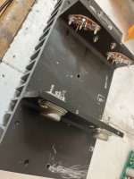
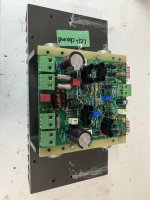
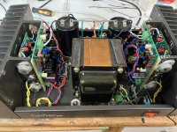
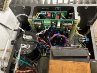
This is more than an upgrade kit - this is pretty much a whole new amplifier - the only things re-used are the transformer and chassis, and maybe the filter capacitors (I had replaced mine a few years back and they're fine so they stayed) and some hardware and fuse holders. Oh, and the 8 MOSFETs.
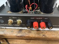
Everything else was stripped out including the ridiculously bad input jacks, and the even worse quality speaker connectors.
I replaced the former with some gold isolated RCA jacks and the latter with some halfway decent binding posts, making sure to keep them isolated from the chassis.
The MOSFETS were all removed, and I threw away the mica insulators and old brittle sockets, replacing with with new pieces from Digikey along with fresh heat sink coupling compound.
Attached photos show the stripped out chassis, and the initial progress - new hardware and newly re-mounted MOSFETS.
Thing is, the DH-220 was doing workshop-sound-system-duty so I never bothered to take it apart for a good part of a year.
A few weeks ago I finally swapped it out for a Harmon Kardon receiver (it more or less sucks in comparison, sonics-wise) and got dismantling.
This is more than an upgrade kit - this is pretty much a whole new amplifier - the only things re-used are the transformer and chassis, and maybe the filter capacitors (I had replaced mine a few years back and they're fine so they stayed) and some hardware and fuse holders. Oh, and the 8 MOSFETs.
Everything else was stripped out including the ridiculously bad input jacks, and the even worse quality speaker connectors.
I replaced the former with some gold isolated RCA jacks and the latter with some halfway decent binding posts, making sure to keep them isolated from the chassis.
The MOSFETS were all removed, and I threw away the mica insulators and old brittle sockets, replacing with with new pieces from Digikey along with fresh heat sink coupling compound.
Attached photos show the stripped out chassis, and the initial progress - new hardware and newly re-mounted MOSFETS.
Attachments
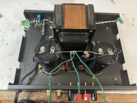
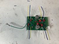
The circuit boards were pretty busy! The driver board is quite densely populated. Fortunately, the included bill-of-materials was pretty good and allowed me to find what I needed through a combination of Digikey and Mouser shopping. I have to say that electronic component shortages are still being felt - the inventory levels were down at both sellers, and many parts were out of stock and I had to use substitutes in some cases where I couldn't find what I needed from either.
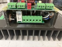
Instead of fly-wiring the output circuitry, there is a nifty PCB for that which is mounted underneath the driver boards in between the MOSFETS.
The instructions say to use solid wire to hook them up and to keep the wires as short as possible - a sensible measure to reduce inductance but also necessary because it's the wiring itself that holds this board in place. There are four little feet that keep it off the heatsink. Whoever designed this board did a lot of experimenting before arriving at a final design. I'm still not 100% comfortable with a PCB floating in mid-air but it seems to be solid enough in place with short wiring.

The driver board is the same size as the original driver board and will mount right in place.
A nice touch, for building - albeit they're all failure points over time - are the screw-terminal strips to connect the input board to the output board and to the rest of the amp - the power supply, input and output jacks and whatnot.

Instead of fly-wiring the output circuitry, there is a nifty PCB for that which is mounted underneath the driver boards in between the MOSFETS.
The instructions say to use solid wire to hook them up and to keep the wires as short as possible - a sensible measure to reduce inductance but also necessary because it's the wiring itself that holds this board in place. There are four little feet that keep it off the heatsink. Whoever designed this board did a lot of experimenting before arriving at a final design. I'm still not 100% comfortable with a PCB floating in mid-air but it seems to be solid enough in place with short wiring.
The driver board is the same size as the original driver board and will mount right in place.
A nice touch, for building - albeit they're all failure points over time - are the screw-terminal strips to connect the input board to the output board and to the rest of the amp - the power supply, input and output jacks and whatnot.
Attachments

Thanks Baldrick for doing this. Very interesting and I am considering doing this same change to my DH-220. Do you plan on commenting about the finished sound when done? I’m surprised by the parts shortages you ran into.
Rick
Rick
Well done, @baldrick. The build is absolutely worth the effort, time, and consideration. Take apart that perfectly good amp, by all means. The DH-220C takes those old lateral FETs into the 21st Century. Bob and Rick obviously put a lot of time into the design and documentation.
I will not part with my DH-220C. It is a great amp and my go-to for higher power output.
I will not part with my DH-220C. It is a great amp and my go-to for higher power output.
+1 on any sonic comments comparing Bob’s complete revision of the DH220 vs what other amps you have in your stable. What interests me in this design is the use of lateral mosfets in the output stage and tricked out JFET input stage.
Thanks,
Anand.
Thanks,
Anand.
I fully plan on commenting on the sonics of the finished amplifier.Thanks Baldrick for doing this. Very interesting and I am considering doing this same change to my DH-220. Do you plan on commenting about the finished sound when done? I’m surprised by the parts shortages you ran into.
And I'm not surprised about parts shortages. It's three years on and it's not getting any better at any of the shops. Even things as mundane as 1 watt 1% resistors are scarce unless they're historic "standard" values like 3.3K 33K 330K and so on.
Baldrick did you reuse the output fets or get Exicons? I will probably stick with the originals for now.
Thanks again, Rick
Thanks again, Rick
The originals all tested fine using the basic tests that Bob Cordell described, so they'll stay in. New Exicon MOSFETS are expensive. If you know of a decent source I'm all ears, but I don't really have the penchant (or the test gear) for buying a whole bunch from the UK and matching them and rejecting the un-matchable ones.
Even though the AudioXpress article tells it otherwise, I'd omit those TO-3 transistor sockets in order to increase reliability and solder the wires directly to the transistor pins and solder lugs, respectively.
After having read that much positive reports on Bob Cordell's replacement boards, I'm eager to rebuild my 40 years old Elektor Crescendo's, using his design. But the necessity of separate output transistor boards makes it almost impossible, as the Crescendo PCB has the Hitachi's in line.
Best regards!
For more idea and mods about this amp, see the huge thread below
https://www.diyaudio.com/community/threads/hafler-dh-200-220-mods.31131/
https://www.diyaudio.com/community/threads/hafler-dh-200-220-mods.31131/
This process has taken a while. There were a number of snags in the process which ended up in fried components.
Some very unexpected fried components, too, like the float resistors to the chassis on the speaker terminal negative terminal and the float resistors to ground on the input negative.
Anyway, I finally think I have got this running and the initial tests are impressive. I drove this to well over 120 watts with a clean signal and no oscillation.
And the initial sound through the speakers is impressive as well. This is not your dad's dusty old DH-220. This is something altogether different.
Still on the workbench but I think I might button it up this week.
Baldrick are the snags something in the documentation? I would be very interested in more on the sound quality you noticed.
Rick
Rick
This is a complex kit. There are three sources of documentation for it, which doesn't help.
There's the AudioXpress article, the material on the cordellaudio.com site and the documentation that you're given when you purchase the kit.
None are 100% definitive and assume that the user is highly experienced, which I suppose is fair. Reading all three is important but there is a lot of crossover between them. A more step-by-step instruction manual with better photography would be welcome for those with less experience.
What we are doing, in essence, is building up a brand new amplifier from bare PCBs and component parts, reusing only the chassis, output devices, transformer, power supply caps and bridge rectifier. Ideally, you'd replace all the output devices, too, but the reading material available gives you rudimentary methods to test the output devices and offers a somewhat crude, but effective way to make sure they're matched and more-or-less in-spec.
People have built all new amplifiers out of these boards, with brand new Exicon lateral MOSFETs on home-built chassis, transformers and heatsinks.
Kudos to the designer who made sure that these operate on a wide range of supply voltages and depending on the output device arrangement and quantity (up to three pairs per channel) can supply in excess of 300 watts per channel.
The input PCB uses a LOT of very compact components and packs them in very tightly to fit in a form factor similar to the original input cards on the amplifier, so soldering skills are critical for success.
I consider myself excellent at soldering and rework, but I'm not an ECE or electronics tech, just a hobbyist, and quite frankly I sometimes find solid state work a bit intimidating, preferring the simpler world of tubes. But here we are.
Sonically, my first impressions are quite positive. We have to assume that this is a brand new, non-broken-in amplifier.
I've only run it for a few hours. But on my workshop speaker (minimonitors) system, which sounds pretty good for near-field listening, I am very impressed with the sound of this. Source material up to now has only been Compact Discs so I can't comment much more on the sound of it right now until it's closed up, and sitting in the big-boy setup in the living room.
Thought I'd let you guys know that I'm going to button this up and stick it in service for a while.
The tests all looks pretty good.
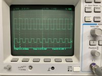
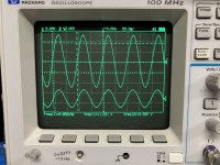
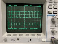
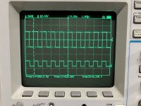
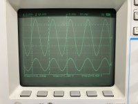
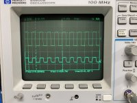
Including some nice looking square waves at 1 and 10 KHz and a pretty impressive run at 10 KHz on a clean sine wave all the way to 34 volts RMS at 8 ohms. So 146 watts. I don't have a distortion analyzer but any more than this and it clips, so I presume this is hitting at least 1% distortion at this point. Rail-to-rail voltage during the test was 120v even.
(I am using a x10 probe in that test. All the other tests are with a x1 probe)
And I'm digging the sound so far.
The tests all looks pretty good.
Including some nice looking square waves at 1 and 10 KHz and a pretty impressive run at 10 KHz on a clean sine wave all the way to 34 volts RMS at 8 ohms. So 146 watts. I don't have a distortion analyzer but any more than this and it clips, so I presume this is hitting at least 1% distortion at this point. Rail-to-rail voltage during the test was 120v even.
(I am using a x10 probe in that test. All the other tests are with a x1 probe)
And I'm digging the sound so far.
Attachments
-
 CH-1 1 KHz Squarewave.jpg402.4 KB · Views: 154
 -
 CH-1 10 KHz Sinewave.jpg440.6 KB · Views: 137
 -
 CH-1 10 KHz Squarewave.jpg408.6 KB · Views: 129
 -
 CH-2 1 KHz Squarewave.jpg372.1 KB · Views: 129
 -
 CH-2 10 KHz Sinewave.jpg357.3 KB · Views: 134
 -
 CH-2 10 KHz Squarewave.jpg426.6 KB · Views: 166
 -
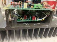
 whole amp assembled.jpg602.7 KB · Views: 218
 -
 right channel assembled.jpg518 KB · Views: 183
I am using a x10 probe in that test. All the other tests are with a x1 probe)
@baldrick
Nice measurements. With your sinewave measurements, was probe 2 the 10X probe? If so, then the gain works out to 28-29 dB, similar to your square wave response.
Great job troubleshooting and getting the whole enchilada to work!
Thanks,
Anand.
Yes, correct. That is a pretty good gain for a 40 year old amp (well a new amp in a 40 year old shell).With your sinewave measurements, was probe 2 the 10X probe? If so, then the gain works out to 28-29 dB, similar to your square wave response.
- Home
- Amplifiers
- Solid State
- Hafler DH-220 - Taking apart a perfectly good amp