I have a early '90s Hafler 915 preamp in perfect working order. It is smooth and musical, but not the most detailed. Anyway, I like its sound very much in my system.
Would I benefit with replacing the two 4700 mfd 35v polarized electrolytic caps in the power supply (large black caps in upper left of photo) to something better? What would your recommend (they are short and wide)?
Would I benefit with replacing the two 4700 mfd 35v polarized electrolytic caps in the power supply (large black caps in upper left of photo) to something better? What would your recommend (they are short and wide)?
Attachments
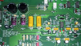
depends... what brand are they? can you show other side of caps in question. -try to find ones which have lowest Z at highest frequency. -- RNMarsh
Thanks Mr Marsh,
I was too lazy to open it up to take better photos so I found one on the web. But, the caps are a non-specific brand?
What do you mean by 'low Z'.
All I find are electrolytic in my search. Is there a better option, or is it ok to get a better electrolytic cap?
Lastly, should I up the mfd to a higher value than 4700 mfd, 35 volt?
Most important is to get caps that physically fit so check the data sheets of any you are looking at for size and pin spacing.
Low Z or low E.S.R. denotes a low internal impedance. That is perhaps more applicable to switching type supplies rather than linear ones such as this. I wouldn't increase the value at all and yes, any caps will be electrolytic types. Go for a reputable brand rather than a "generic" unspecified device.
(I suspect there is probably no benefit to be obtained by swapping these)
(I suspect there is probably no benefit to be obtained by swapping these)
Thanks Mooly,
I was wondering about this. Musical Design, who in part helped design this preamp of which their caps are used in it, also makes a mod for it. But the basic mod costs 399.00 and he is not volunteering what he does so I can perform the mod myself. I guessed the power supply caps where part of the mod, hence my interest in swapping 'em out, but I'm not anxious to do extra work for nothing.
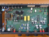
Ok, I'm back with one more question. Here is a photo of my actual preamp (earlier photo is not my unit).
I now see that mine has not been modded like the first photo posted earlier. The 8 other yellow Musical Concept caps populating the other 915 preamp are .1 mfd 100v polypropylene caps (8 of them). I figure if I replace these I may have one of John Hillig's mods to my preamp. He is not willing to sell the parts only and I don't want to invest the $399 he asks for his basic mod. What brand would you recommend to use to make the upgrade?
I now see that mine has not been modded like the first photo posted earlier. The 8 other yellow Musical Concept caps populating the other 915 preamp are .1 mfd 100v polypropylene caps (8 of them). I figure if I replace these I may have one of John Hillig's mods to my preamp. He is not willing to sell the parts only and I don't want to invest the $399 he asks for his basic mod. What brand would you recommend to use to make the upgrade?
Attachments
I'm afraid I'm not a believer when it come to "boutique" parts so can't really advise you on that one 😀
Those type of caps don't really deteriorate or change like electros do.
Those type of caps don't really deteriorate or change like electros do.
Interesting, on this site folks talk about the advantages of better caps.
Indeed, and resistors too. The debates run and run. Me... I'm content to choose and use good quality "commercial" grade parts of known provenance. What I look for in terms of sound quality comes more from the circuit topologies I prefer to use.
Hey 😀 but don't let what I say or think stop you from experimenting.
had a similar experience with my Forte 44 discrete JFET preamp. The Forte 44 is a discrete JFET linestage designed and built by a now defunct spin-off company of Threshold. I thought the uit sounded pretty, until I completely removed it from the signal chain by connecting my low output level home brew DAC directly to my power amp. Wow, what an improvement! The sound is now SO MUCH better that, for now, I've forgone the connivence of even a volume control.
In looking at the 915 schematic, IMHO, Hafler has made generous use of quality JFETs, and simple yet smart circuit discrete topologies. They only places they appear to have taken the easy route is for the voltage regulators, and the headphone amplifier, both of which are IC implementations. I'm not certain about where you would obtain the improvement you seek. Perhaps, the capacitors, or perhaps the volume controls, or perhaps the power supply implementation, or perhaps somewhere else. Sometimes, it's less of a headache to simply obtain a different, more satisfactory sounding component.
If you do not already possess a copy of it, here is the link to the 915's service manual which includes schematics. Courtesy of, 'mlloyd1'. http://www.hafler.com/techsupport/pdf/Series915_preamp_man.pdf
Last edited:
DAC directly to my power amp. Wow, what an improvement! The sound is now SO MUCH better that, for now
Hafler has made generous use of quality JFETs, and simple yet smart circuit discrete topologies. The only places they appear to have taken the easy route is for the voltage regulators, and the headphone amplifier, both of which are IC implementations.
Ken,
I've experienced the same thing with a Benchmark DAC w variable output direct to a AES tube power amp. I used it this way for a long time until I needed analogue input in particular a phono. BTW, here is a photo of Hafler simple phono stage which sound quite nice to me.
The headphone section is quite pitiful and don't use it.
Lastly, the preamp has opened up quite a bit from its 4 year period of non-use. What would you recommend to improve the power supply?
Mike
Attachments
Hi, Mike,
I suppose, you could try applying the usual suspects of generic DIY power supply mods. You know, audiophile e-lytic caps., newer 3-terminal regulators., etc. However, as I indicated is my experience, sometimes (rather often, actually) it's simply less of a headache to replace the component for something which you positively know sounds better, to you. This can even be a less costly route than 'upgrading' your 915 with premium priced audiophile parts. Upon completion of an upgrade, you still may not have obtained the subjective improvement you had hoped to. True, you wouldn't learn as much, nor get the fun and sense of accomplishment that comes from modifying your own equipment, but you just may end up getting more enjoyment from actually listening to music. 🙂
Sorry, that I'm not able to guide you better on this. 🙁
Ken,
....The headphone section is quite pitiful and don't use it.
Lastly, the preamp has opened up quite a bit from its 4 year period of non-use. What would you recommend to improve the power supply?
Mike
Mike,
I took another look at the 915's schematic. I did notice one particular detail of the power supply implementation that we don't find often utilized in more recent products. Which is, that all amplification blocks appear to directly wired to the same +15V, -15V supply rails. I didn't readily find any provision even for passive decoupling of noise and inter-stage power supply disturbances, only local passive bypassing. It's pretty much standard practice today to find multiple independent supply regulators, or, at the least, passive decoupling being utilized to isolate supply rail induced disturbances between circuit blocks. I'm not sure there is much you do to change this without hacking up the PCB traces, possibly damaging the unit and rendering it worthless even to re-sell.
I can fully believe that the headphone section sounds none too pleasing. It is comprised of an single NE5532 op-amp per channel. It features a 150 ohm current limiting resistor, placed between the 5532 and the output jack. This effectively sets the output impedance at 150 ohms. This is too high for many audiophile headphones. Hafler might have utilized two or more NE5532s in parallel (many hands make for light work) to help deliver enough current to enable use of much lower value current limiting resistor, and increase total power dissipation capability. The additional cost and implementation trouble would have been minimal, I should think. On top of all that, the circuit appears to be connected directly to the same supply rails as every other gain block in the unit. Seems like incongruous cost based shortcutting, given the nice discrete JFET circuitry included elsewhere in the unit.
Last edited:
Mike,
I took another look at the 915's schematic. I did notice one particular detail of the power supply implementation that we don't find often utilized in more recent products. Which is, that all amplification blocks appear to directly wired to the same +15V, -15V supply rails. I didn't readily find any provision even for passive decoupling of noise and inter-stage power supply disturbances, only local passive bypassing. It's pretty much standard practice today to find multiple independent supply regulators, or, at the least, passive decoupling being utilized to isolate supply rail induced disturbances between circuit blocks. I'm not sure there is much you do to change this without hacking up the PCB traces, possibly damaging the unit and rendering it worthless even to re-sell.
I can fully believe that the headphone section sounds none too pleasing. It is comprised of an single NE5532 op-amp per channel. It features a 150 ohm current limiting resistor, placed between the 5532 and the output jack. This effectively sets the output impedance at 150 ohms. This is too high for many audiophile headphones. Hafler might have utilized two or more NE5532s in parallel (many hands make for light work) to help deliver enough current to enable use of much lower value current limiting resistor, and increase total power dissipation capability. The additional cost and implementation trouble would have been minimal, I should think. On top of all that, the circuit appears to be connected directly to the same supply rails as every other gain block in the unit. Seems like incongruous cost based shortcutting, given the nice discrete JFET circuitry included elsewhere in the unit.
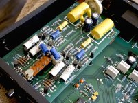
I have an SE100 which I modified with CRC filtering on the stock rails to help decouple the channels from each other. The SE100 design had provisions that allowed rail resistors to easily be installed and the traces cut. I used 8.2 ohm 1 W resistors here. The SE100 was the precursor to the 915 and utilized a very similar line stage circuit, so Hafler might have implemented this feature on the later 915 as well. I looked at the pictures posted of the 915 and I do not see it there from the top, but its possible there might be something on the backside of the board.
I posted a picture of my modded SE100 with the rail CRC resistors installed, for those that have trouble spotting them. They are the 4 larger light blue ones in the center of the board. Two of them are sitting vertically and have their wires soldered together, the other two are laying down horizontally.
For the headphone output, I just pulled the NE5532, I don't use the headphone output and the NE5532 was just another draw on the little stock 6VA rated transformer that was not needed. I have everything on my work bench tied through a Kill-a-watt meter and the power draw dropped from 3 VA TO 1 VA after the NE5532 was removed. I know that the kill-a-watt is not exceptionally accurate at this low level, but I was a bit surprised that it registered that much of a power drop with the 5532 in the circuit.

Last edited:
I compared your SE100 to my 915 and there are quite a few similarities. Looks like the 915 has a few more op amps.
Did you notice any sonic improvement by removing the headphone opamp?
The area that you added your resistors is quite similar w/ the 915 also including an additional opamp.
BTW, did you substitute the factory poly caps w/ Wima. That would be an easy change for me to do, but I'm not sure if it will offer any sonic benefits. What do you think?
I compared your SE100 to my 915 and there are quite a few similarities. Looks like the 915 has a few more op amps.
Did you notice any sonic improvement by removing the headphone opamp?
The area that you added your resistors is quite similar w/ the 915 also including an additional opamp.
BTW, did you substitute the factory poly caps w/ Wima. That would be an easy change for me to do, but I'm not sure if it will offer any sonic benefits. What do you think?
I did not check the before and after sound of the preamp with the NE5532 removed. It would be easy enough to do just remove it and try it out.
I did replace 6 of the caps in the linestage. They were originally evox polycarbonate's and I swapped them for Wima Polypro's. Yours in the 915 however are already the better quality polypro film caps and I cannot see you getting any benefit by swapping them out for Wima's.
Unfortunately most of the circuit is already pretty decent, so tweeking gets harder. You could try swapping out some of the critical resistors in the line stage for low noise Dale RN60's. Beyond that you will have to start looking at building up a different power supply and ditching the 7815/7915 regulators. Or depending on your skill level you could use your input stage buffer as a passive preamplifier. That is what I did with my SE100 (actually I added the buffer the 915 already has it) and I posted a thread on this today.
- Status
- Not open for further replies.
- Home
- Source & Line
- Analog Line Level
- Hafler 915 preamp cap question