A while back I ask here in the forum if I can parallel two power supplies to power the chipamp. One power supply had just perfect voltage, but not enough current, there was distortion in the peaks in dynamic music and trafo itself was getting warmer and warmer.
Luckily, I had two identical ones, so I paralleled them, and life is good. Highly recommended.
However, I have many other projects. Here are some other tricks I learned.
I had quite a powerful 12 volt dc switching power supply, so I tried to use it as heater source for tube amp (two stereo 6 volt section in series). It worked, but I was hearing some buzzing sounds inside the tubes, and that is even without high voltage. I always preheat first. So I was wondering how to get rig of this buzzing, which, I am not sure, may be harmful to the filament. You can not connect any big cap to switching supply, it shuts down. However, if you treat it like its high frequency AC, and you put full diode bridge, then you can place any capacitor value after the bridge, and truly create DC. You may end up with slightly different voltage, but for the heaters, that is perfectly fine. Remember, you are not galvanically isolated.
In other case, I had two 19.5 volt DC switching supplies, so I did the same, placed full diode bridge to each, then big caps for filtration (do not remember now, can check later, but a lot), connected minus of one to plus of the other to create ground, and now I have +/- ~19 volts DC, perfectly filtered, for chip amp. Remember, no galvanic separation. The other thing I did was I chopped of the AC lead, and connected both to one AC power outlet, as not to have two power cords. That would be awkward to turn it on at the same time.
Ok, one more.
I was experimenting with tube amp, and I needed high voltage AC of ~250 volts. I had no such transformer around, so I came up with this neat solution. I had plenty of transformers, which are 120 volts in, 30 volts out. From old amps. So I connected first trafo to the wall, normally, took 30 volts AC and plug it straight to 30 volts AC on second trafo, and since second trafo had two secondaries to allow 120/230 option, I wired it to give me ~ 230 volts. Good enough to rectify and use it for tube amp. Works like charm. And now we are galvanically separated, even double!
Ok, enough for now. Disclaimer, I am no expert in this, just diy fanatic.
Last edited:
A mains powered AC to DC SMPS usually has the 0volt output connected to the metal enclosure/case and that in turn MUST be connected to the Mains PE. This is easy to check using a continuity meter.
If you use two of these SMPS, then they are not isolated, both have 0volts connected to PE.
You cannot connect two of these standard SMPS in series. The PE connection of one will short out the output of the other.
If you use two of these SMPS, then they are not isolated, both have 0volts connected to PE.
You cannot connect two of these standard SMPS in series. The PE connection of one will short out the output of the other.
Last edited:
Hi Andrew, what you say is absolutely correct. If the SMPS has grounded metal case.
However, I will take few pictures of what I mean and how it works for me. Those two 19.5 DC switching supplies are both from sony computers, they are both in black plastic box, no ground connected anywhere. When I hooked plus of one to the minus of the other, creating new ground, nothing bad happened, and all kept woking fine, I was able to measure close to 40 volts now between negative and positive.
The chip amp works just fine. I will take few pictures soon.
Rewording your advice should provide guidance to any Builder.
Some plastic encsed SMPS use a 3pin mains socket.
Some of these connect PE to the internal parts.
One MUST check that both outputs are isolated from PE.
Some plastic encsed SMPS use a 3pin mains socket.
Some of these connect PE to the internal parts.
One MUST check that both outputs are isolated from PE.
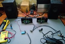
Andrew, as promissed, here are two pics. Two 19.5 volt smps supplies hacked together to provide +/- 19 volts. It has been playing for a week or so on chip amp, great sound. I would not post it if it would not work. Sometimes you get lucky!
Attachments
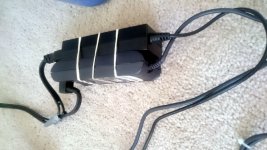
One mains cable looks flattish, meaning 2core. That will need to be feeding a ClassII device which CANNOT have zero volts connected to Earth.
I can't make out the other cable type. You need to check that it too is not connect Earth to Output.
Other wise you could short one of the supplies when you connect to a ClassI amplifier
I can't make out the other cable type. You need to check that it too is not connect Earth to Output.
Other wise you could short one of the supplies when you connect to a ClassI amplifier
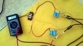
Ok, here is one more neat trick, not from my head, just from outhere. So I have quite a few transformers with one single secondary, but I need symetrical power supply, ideally +/- 20 volts for my experiments with chip amps. I found few 30VAC trafos, so I put together this neat two transistor, two resistor circuit to make symetrical supply. Works great, and its safe (for a change).
Attachments
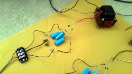
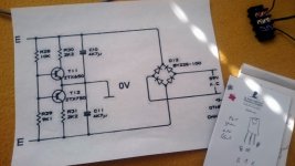
Btw i know off course how to do symmetrical supply from one secondary, but that would from 30 vac resulted in way too high voltages...just for clarification.
old thread, but this is yet another switching power supply hack
i put together small jlh amp, based on mosfets, ebay kit
when i adjusted the 1/2 power supply on output cap and the mosfet current with normal linear power supply, i thought i will try switching power supplies, just like for ACA
however, since there is big cap on the board, switching supplies did not like it
they were farting at first and then they turned off
so as before, insted of connecting them directly, i first fed the 19.5 volts to rectifier bridge, then to the amps
now no problem! now the switching supplies like it, and do not even break sweat
nice little amp btw
Attachments
Last edited:
Uh, thanks. 19.5 vdc switcher supplies are surplus since the laptop computers they come with wear out the disk drive, and new parallel ATA disk drives are no longer available. Not safety grounded either pin, and AC connector only has 2 pins. Was planning to power a class D amp board with them, but it will require local capacitance that as you say, the supply may not like. Understand the bridge rectifier before parallel capacitor trick.i thought i will try switching power supplies,
however, since there is big cap on the board, switching supplies did not like it
they were farting at first and then they turned off
so as before, insted of connecting them directly, i first fed the 19.5 volts to rectifier bridge, then to the amps
now no problem! now the switching supplies like it, and do not even break sweat
I've picked up a couple of dozen small supplies at $1 each at the charity resale shop. Never have I found one yet that either load pin is connected to the fat (neutral) AC blade. Now that transformer supplies are blowing away in the wind, I may have to learn to deal with switcher supplies for $1.
In other case, I had two 19.5 volt DC switching supplies, so I did the same, placed full diode bridge to each, then big caps for filtration (do not
remember now, can check later, but a lot), connected minus of one to plus of the other to create ground, and now I have +/- ~19 volts DC, perfectly
filtered, for chip amp. Remember, no galvanic separation. The other thing I did was I chopped of the AC lead, and connected both to one AC power
outlet, as not to have two power cords. That would be awkward to turn it on at the same time.
Thank you for sharing your experience.
I'm trying to connect two hp laptop adapters to get 19 0 -19 in order to power LM1875 mono board.
However, when I connect them together in a series one supply seems to get disabled.
I've not connected their earth pin to 230V power socket. Also I've used diodes across outputs.
what could be the reason behind this ?
Also could you share a rough diagram of bridge rectifier + capacitor connections to power supply.Its hard to clearly understand the connections
from attached picture.
Many Thanks
secondaries can be paralleled if they have same number of turns.
if they dont they start pulling a lot of current.
i made a smps transformer and used multiple secondaries to get around skin effect.
i found on no load it was pulling a lot of current.
turned out secondaries werent exactly same length.
if they dont they start pulling a lot of current.
i made a smps transformer and used multiple secondaries to get around skin effect.
i found on no load it was pulling a lot of current.
turned out secondaries werent exactly same length.
That´s why bifilar winding is recommended.turned out secondaries werent exactly same length.
- Home
- Amplifiers
- Power Supplies
- hacking the power supplies