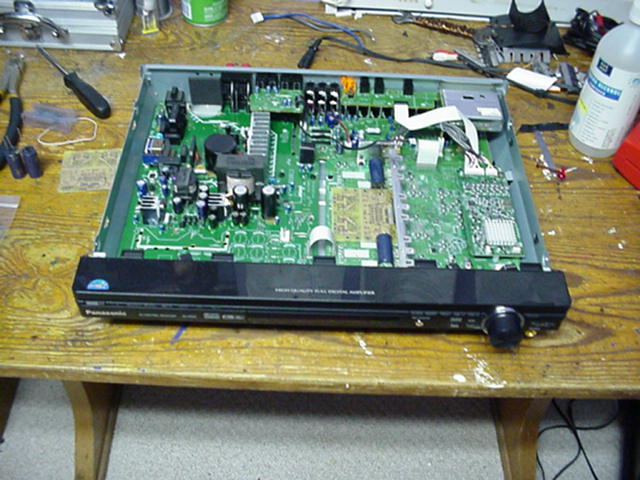
I was very impressed and inspired by hifiZen's NS500V mods in this thread. So I decided to do these on my player--however, I'm using DVP-NC650V, the 5-disc carousel version of the NS500V. Its design is similar but not identical.
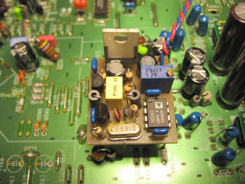
For your reference, here are two pictures of the audio PCB:
Labeled photo
Sharper unlabeled photo
So far, I have successfully removed/bypassed C247 and C248 (hifiZen bypassed the same-numbered capacitors). However, I still wonder if I should instead have removed C253 or C254 instead (basically, which caps belong to which Output, #1 or #2)... maybe I should desolder my cap bypasses and see which output gets muted?
My other questions:
1) Where to get the parts (preferably cheaply)? hifiZen mentioned using:
* Analog Devices AD8620 opamp
* two 1uF Panasonic HF decoupling caps (he implied HFQs would be even better)
* see below, a Holco resistor is used--basically, I need a good 30-ohm resistor for my purposes here
2) Any advice on finding the equivalents of hifiZen's other mods? It's pretty obvious how to change the opamp and to kill neighboring muting transistors. However, what about bypassing the output resistors, like so (post by dorkus):
So then... I should look for the output pad and connect directly to the terminal's contact (visible in my pic)?
Any help or suggestions welcome!
--Leo
For your reference, here are two pictures of the audio PCB:
Labeled photo
Sharper unlabeled photo
So far, I have successfully removed/bypassed C247 and C248 (hifiZen bypassed the same-numbered capacitors). However, I still wonder if I should instead have removed C253 or C254 instead (basically, which caps belong to which Output, #1 or #2)... maybe I should desolder my cap bypasses and see which output gets muted?
My other questions:
1) Where to get the parts (preferably cheaply)? hifiZen mentioned using:
* Analog Devices AD8620 opamp
* two 1uF Panasonic HF decoupling caps (he implied HFQs would be even better)
* see below, a Holco resistor is used--basically, I need a good 30-ohm resistor for my purposes here
2) Any advice on finding the equivalents of hifiZen's other mods? It's pretty obvious how to change the opamp and to kill neighboring muting transistors. However, what about bypassing the output resistors, like so (post by dorkus):
i actually went one step further - i conncted a 100 ohm Holco directly from near the opamp output pad to the output terminal, using teflon tubing to insulate the resistor leads. this way you can avoid the flimsy PCB traces and extra solder terminals and use a better quality resistor. i'll try taking a picture sometime, once i get the thing working again...
So then... I should look for the output pad and connect directly to the terminal's contact (visible in my pic)?
Any help or suggestions welcome!
--Leo
For reference, here is hifiZen's main list of mods:
---------------------------------
A couple more questions:
3) In HifiZen's first pic, are the black opamp decoupler capacitors soldered in place of removed mute transistors? It's hard to tell from the picture where the mute transistors were removed.
4) What does "remove C280 and C281 (220pF) caps to ground" mean?
Thanks,
--Leo
1st mod: new opamp - I replaced the crappy one with an Analog Devices AD8620... very worthwhile! I also added 1uF Panasonic HF supply decoupling caps (no HFQs on hand...).
short out C247 and C248 (47uF electrolytics) output coupling caps with a small piece of trimmed component lead
- bypass R288 and R289 (470ohm each) series output resistors by stacking a 10ohm resistor on top.
- remove muting transistors Q213 and Q214
- remove C280 and C281 (220pF) caps to ground
- bypass R323 and R325 (470ohm) series output resistors with 0ohm resistor stacked on top
---------------------------------
A couple more questions:
3) In HifiZen's first pic, are the black opamp decoupler capacitors soldered in place of removed mute transistors? It's hard to tell from the picture where the mute transistors were removed.
4) What does "remove C280 and C281 (220pF) caps to ground" mean?
Thanks,
--Leo
Leo,
Thanks for the compliments! So let's see here...
Boy, that analog board looks a lot like the NS500 one! I got the schematics by ordering the service manual straight from Sony... you may be able to do the same, but I don't have a part number for the 650V. The service manual was quite affordable - maybe $30 or so.
AD8620 should be available from Newark and Allied Electronics (both carry Analog Devices, AFAIK), but don't seem to show up on their web sites. You may also be able to get them as samples(?). Actually, if anyone else knows of a good supplier for Analog Devices parts, I'd like to know! You could also use the OPA2134, which should sound excellent here as well, and seem to be easier to obtain.
The mute transistors were removed from the two larger circles shown at the upper right side of the image, near the chassis metal. There was nothing put in their place. The big decoupling caps were actually soldered right in place over the existing ceramic chip decoupling caps... if you look closely you'll see them still there at the ends of the cap leads.
C280 and C281 were located in the circles next to the silkscreen labels C277 and C278. Confused? Me too. I hope I didn't get those part numbers wrong. Anyway, they were a shunt to ground after the series output resistor. From the pics of your board, you don't seem to have these caps, so I wouldn't worry about them.
If I were smart, I would have colour coded the pictures like yours... oh well. Next time.
Chad,
Great to hear from you in person!
I called up both AD suppliers, but neither had the parts. I also found this surprising itty-bitty over at SACDmods (the people who charge over $300 for ns500v mods: )
Is he serious? Both you and Marc seemed to like your "upgraded" opamps better than the 4558. I'll look for the OPA2134, I just couldn't help the curiosity after reading this.
Also wondering, what NS500 settings do you use? I heard some people enable the "CD Direct" option to bypass unnecessary circuitry during playback. I'm wondering if that would also bypass any upsampling circuitry, which could be a bad thing. I just want to make sure all the "easy tweaks" are done right first 😉
Anyway thanks for all the feedback!
Leo
Great to hear from you in person!
I called up both AD suppliers, but neither had the parts. I also found this surprising itty-bitty over at SACDmods (the people who charge over $300 for ns500v mods: )
The stock op-amps beat even the Analog Devices AD-8620 which I was evaluating as a replacement, and along the way I stumbled upon a two resistor tweak to bias the op-amps in to class A. This improves high-end clarity by quite a bit. Front channels only.
Is he serious? Both you and Marc seemed to like your "upgraded" opamps better than the 4558. I'll look for the OPA2134, I just couldn't help the curiosity after reading this.
Also wondering, what NS500 settings do you use? I heard some people enable the "CD Direct" option to bypass unnecessary circuitry during playback. I'm wondering if that would also bypass any upsampling circuitry, which could be a bad thing. I just want to make sure all the "easy tweaks" are done right first 😉
Anyway thanks for all the feedback!
Leo
I just removed what I believed were the mute transistors: Q214 and Q215 as seen in the picture. However, to my surprise I didn't hear any power on/off transients! Just same normal operation. Any way to explain this?
Thanks,
Leo
PS: Any other parts to get at Newark besides the OP2134? (Still looking for those 2 capacitors and resistor..)
Thanks,
Leo
PS: Any other parts to get at Newark besides the OP2134? (Still looking for those 2 capacitors and resistor..)
Leo,
That is the part that you are looking for. You can get 3 free samples of the opa2134 at ti.com and you can get 2 free samples of the ad opamps at analog.com That way, you can try the devices and see what ones you like before going and buying from newark.com
That is what I have done.
--
Brian
That is the part that you are looking for. You can get 3 free samples of the opa2134 at ti.com and you can get 2 free samples of the ad opamps at analog.com That way, you can try the devices and see what ones you like before going and buying from newark.com
That is what I have done.
--
Brian
Neat, I just ordered 2 samples of each. Thanks a lot Brian! The samples are identical to the real thing, right?
Which do you think is "better" for the NS500V/NC650V, the OPA2134 or AD8620? It would be very painful to solder/desolder both...
Thanks,
Leo
Which do you think is "better" for the NS500V/NC650V, the OPA2134 or AD8620? It would be very painful to solder/desolder both...
Thanks,
Leo
***UPDATE*** I just downloaded NC650V's schematics, and posted them here:
block diagram (71KB)
detailed diagram (288KB)
full schematic (419KB)
As you can see, there are a couple differences from NS500V! Any observations? I removed the correct muting transistors (Q214 and Q215), but I hear no power on/off transient sound. Is that good luck?
--Leo
block diagram (71KB)
detailed diagram (288KB)
full schematic (419KB)
As you can see, there are a couple differences from NS500V! Any observations? I removed the correct muting transistors (Q214 and Q215), but I hear no power on/off transient sound. Is that good luck?
--Leo
Schematics, schmematics
If anyone can advise on a diode mod, here are my PSU schematics:
PSU block diagram #1 (153KB)
PSU block diagram #2 (103KB)
PSU detailed diagram (191KB)
PSU full schematic (342KB)
Back to the output stage... should I just run a Holco resistor directly from the opamp's output pins to the RCA terminal? (The way dorkus did.) Or is there a better way, like running the Holco to the headphone tapping point (so headphones don't get excluded?) What's the 0-ohm resistor doing near the stereo-out, anyway?
Basically, my self-amplified speakers have a "sensitivity" of 800mV (which is considered more sensitive than most non-computer speakers). The NS500/NC650 have 2V output that can be "modulated" to 1V as an option. Does that mean its outputs are "too strong" for my speakers, and I should use a higher-rated Holco (like 1,000ohms) to weaken them?
Thanks,
Leo
If anyone can advise on a diode mod, here are my PSU schematics:
PSU block diagram #1 (153KB)
PSU block diagram #2 (103KB)
PSU detailed diagram (191KB)
PSU full schematic (342KB)
Back to the output stage...
should I just run a Holco resistor directly from the opamp's output pins to the RCA terminal? (The way dorkus did.) Or is there a better way, like running the Holco to the headphone tapping point (so headphones don't get excluded?) What's the 0-ohm resistor doing near the stereo-out, anyway?Basically, my self-amplified speakers have a "sensitivity" of 800mV (which is considered more sensitive than most non-computer speakers). The NS500/NC650 have 2V output that can be "modulated" to 1V as an option. Does that mean its outputs are "too strong" for my speakers, and I should use a higher-rated Holco (like 1,000ohms) to weaken them?
Thanks,
Leo
I would have skipped the headphone (if you don`t plan on using it).
The shorter signalpath you can get, the better sound.
If you don`t overdrive the input on your speaker, keep the 2V output level on your player.
If you drive the speaker input to clipping, then you have to take down the player output. Try with 2V first.
Where did you download the schematics?
The shorter signalpath you can get, the better sound.
If you don`t overdrive the input on your speaker, keep the 2V output level on your player.
If you drive the speaker input to clipping, then you have to take down the player output. Try with 2V first.
Where did you download the schematics?
2002tii said:I would have skipped the headphone (if you don`t plan on using it).
The shorter signalpath you can get, the better sound.
If you don`t overdrive the input on your speaker, keep the 2V output level on your player.
If you drive the speaker input to clipping, then you have to take down the player output. Try with 2V first.
Where did you download the schematics?
Over here. I can send you mine if you want, it's 27mb or so.
I actually do intend to use the headphones, because folks at Head-Fi convinced me to upgrade the onboard phones opamp--it would create a decent entry-level headphone amp.
As for output level, I wonder if higher resistors compensate for the overdrive effect?
Thanks for the link!
You don`t have to mail it to me, don`t think my mailbox likes that file sice 🙂
I tried to download it from your web page, but I only get ca 2Mb before timeout.
I don`t think a higher series resistor will change output voltage noticeably.
I guess you will have to use 2 resistors, one in series with the signal and one from signal to ground.
Don`t remember what it`s called in English...
On Norvegian we call it "spennings deler" = voltage splitter?
- Status
- Not open for further replies.
- Home
- Source & Line
- Digital Source
- Hacking Sony DVP-NC650V (cousin of NS500V), need help/schematics!