Sorry, didn't go through the pages but what's the voltage drop with a gyrator at 10mA?
It is design criterion. You choose working point for your tube, you choose swing, then you choose B+ voltage so voltage drop will be B+ voltage minus what you need on anode at idle (actually, half-swing, or maximal amplitude value, minus minimal voltage drop that you can allow for particular design of your gyrator).
Thanks Ale, I'll look for the thread. Meanwhile what kind of effective resistance can I expect from a gyrator used as an anode load?Paul,
If you look at the threads I started on 4p1L preamp, help with gyrator and other for example there is a lot of good information about MOSFET and Anatoly's Bipolar-MOSFET version for lower quiescent currents (I.e. lower than 10mA).
A good thing to do is to simulate in Spice to check things first and actually helps a lot to understand circuit, etc.
Cheers,
Ale
I am thinking of an active load device here; I know that using a single transistor I'll get somewhere around 500k - 750k which is more than enough as these are differential pairs with cascoded CCS. This is for the low-distortion line stage with the 955s that I built ten years ago and never ran. I have had it running and it is very good indeed, silent with tremendous detail - notably at low level.
I feel it will be better still with active loads which will require a great deal of work... As usual🙄
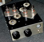
I am writing up the story and I will put it onto the forum with a full circuit diagram with voltages and currents etc. Meanwhile here's a snap!
Paul
Attachments
You don't need any resonances.
What you need, high dynamic resistance in a given frequency band. Say, from 4 Hz to 40 KHz.
What you need, high dynamic resistance in a given frequency band. Say, from 4 Hz to 40 KHz.
I know this is a big request have you design an updated SVCS with current avalible parts . Regards
I know this is a big request have you design an updated SVCS with current avalible parts . Regards
No, nobody asked. And I don't have time now to design anything. However, if somebody helps me to design PCBs for my current project... I mean to draw in software what is needed for manufacturing from my sketch on paper...
Rectifiers, filter caps, voltage stabilizers, gyrators, output transformers. Quite simple, if to have software and to know how to use it. I don't.
Since it your intellectual property send me a private message on we can play with it off the board .
One more thread: pay attention on Michael Koster's version also that uses N-type MOSFET. Advantage of his version is, anode voltage referenced to ground instead of B+ in mine.
http://www.diyaudio.com/forums/tubes-valves/143687-gyrator-question.html
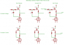
For constant voltage circuits or gyrators using the circuits below the voltage reference mat be either B+ based or ground based.
Constant voltage circuits use depletion mode devices. Constant voltage circuits may use depletion mode or enhancement mode devices.
Zout of the CCS/gyrator is equal to plate resistance in parallel with load.
Zout of anti triode is approximately 1/2 plate resistance in parallel with the load.
Zout of the mu follower is approximately 1/gfs of the MOSFET for relatively high resistor values.
Devices may be cascode to improve dynamic performance.
Attachments
Last edited:
It is fashionable to call everything a girator? 🙂
No.
A gyrator has low impedance on DC to maintain a fixed DC voltage, and high impedance on AC signal voltage.
A gyrator acts like an inductor except for a using a relatively high DC voltage drop instead of storing energy like an inductor does.
Only the top center circuit in my diagram above is technically a gyrator.
It is fashionable to call everything a girator? 🙂
Not everything Svetlana. Only Gyrators. Gyrator - Wikipedia, the free encyclopedia
In this particular case, a device that simulates choke anode load using capacitive reactance.
For constant voltage circuits or gyrators using the circuits below the voltage reference mat be either B+ based or ground based.
Constant voltage circuits use depletion mode devices. Constant voltage circuits may use depletion mode or enhancement mode devices.
Zout of the CCS/gyrator is equal to plate resistance in parallel with load.
Zout of anti triode is approximately 1/2 plate resistance in parallel with the load.
Zout of the mu follower is approximately 1/gfs of the MOSFET for relatively high resistor values.
Devices may be cascode to improve dynamic performance.
Hi Michael,
Thanks for the insight. Hope you can expand here. I may be a bit rusty with circuit analysis, so apologies if I make a mistake in my rationale (just trying to learn here!)
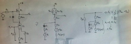
With only one MOSFET I think I can derive the output impedance to be close to 1/Go (see attached) Is this ok?
What would be the impact of the cascode pair in the output impedance?
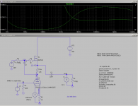
I simulated this simple gyrator at low Id (circa 3.5mA) to fit a 01a preamp and output impedance is about 190 ohms which implies that the Go=5mS at such low drain current. Looking at the DN2540 datasheet the Gfs graph is not that detailed at low currents but should be around 50mS @25mA. Is this correct?
Thanks!!
Ale
Attachments
Thanks to all of you who have replied; I'm afraid I am stony ground here! I have read quite a lot of stuff that I do not understand.
I looked at the specification of a mosfet called IRF820; I could not make head nor tail of it. Ale, you mention an output resistance of 190 ohms? I want something like 200k!
If I go ahead with this I'll probably build a single transistor active load; after all I think I can manage this! I have no need of these giant power devices anyway - I imagine they must have enormous capacitance - I need to pass only about 4 mA, so a MPSA92 should do nicely and with that I can calculate the approximate output resistance - I have to be strict with this as the circuit is a differential pair with cascode CCS and obviously I must not have too high an anode load resistance, but I do want more than the present 97k in the pursuit of ultra-low distortion.
Thanks again to all
Paul
Last edited:
Just done a few sums; the resistance of my CCS is in the order of 28Meg, so I could perhaps use an active load of much higher resistance than the 200k I mentioned in my previous post. Can anyone tell me what the likely output resistance of a constant current source using a fet might be?
Sorry to ask what are probably very basic questions, but I do not understand the specifications of fets and therefore how to calculate the likely output resistance.
Thanks again
Paul
Sorry to ask what are probably very basic questions, but I do not understand the specifications of fets and therefore how to calculate the likely output resistance.
Thanks again
Paul
Paul,
Reading Morgan Jones' book you can get some useful values of the DN2540 to use it in a CCS. The CCS impedance of a single MOSFET is around the setting resistor multiplied by mu (gm*rds). Morgan measured mu from the MOSFET curves as typically rds and gm at the drain current are not specified on the datasheet. For the DN2540 mu is around 4,500 (gm=150mA/V and rds=30K)
Depending on the rset value you need to set the quiescent current, let's say you want to set to 5mA, you need about an rset of 300 ohms, then the output impedance of the CCS is approximately 1.3M. Of course if the CCS is cascoded this impedance can be increased by a factor of rds in theory but you would probably get a CCS with 100Meg or more as the parasitic impedances of the MOSFETs start to contribute here decreasing the impedance of the CCS.
I'm not very knowledgable on this subject, but I think the above rationale is ok, please correct otherwise!
I don't have experience with differential pairs as haven't tried them yet, however I think you need a tail CCS and if you want to balance current on both triodes you need CCS not gyrators as the latter will fix the voltage and with different triodes you will end up with different currents, correct?
So simple CCS or cascoded CCS can be built there if you want to. Can be bipolar ones as perform really well if you don't fancy experimenting with MOSFETs...
Hope this helps?
The output impedance and plate impedance of the MOSFET mu-follower can be analyzed by considering that the MOSFET has an internal source resistance of 1/gfs, which is in circuit between the ideal zero-resistance source and the output source terminal.
Thus the internal source resistance and external source resistance form a voltage divider into, or out of, which the output current flows. This imparts a partial anti-triode like behavior (except 1/gfs is nonlinear) at smaller values of external resistance, as well as allowing the 1/gfs nonlinearity to swamp out desired anti triode behavior in extreme cases. I.e. there is some load current sharing between the tube and MOSFET.
The plate impedance is impacted by the finite gfs because changing output current necessitates a changing g-s voltage across the source resistor. Some fraction of the output signal current is thus "reflected" back to the plate at the ratio of 1/gfs to the external source resistance.
The output impedance is similarly affected because in order to change output current, the voltage across the external source resistor must change, causing a changing current that works into the finite plate resistance of the tube.
The larger the external source resistor, the smaller fraction of the output current reflected back to the tube plate, increasing the impedance seen by the plate and decreasing the output impedance seen at the MOSFET source terminal.
I leave it as an exercise to derive the precise relations... 😉
Last edited:
but you would probably get a CCS with 100Meg or more as the parasitic impedances of the MOSFETs start to contribute here decreasing the impedance of the CCS.
I'm not very knowledgable on this subject, but I think the above rationale is ok, please correct otherwise!
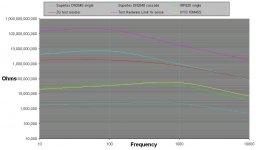
Looks right from the measurements by Gary Pimm.
CCS performance measurments
Attachments
Paul,
Reading Morgan Jones' book you can get some useful values of the DN2540 to use it in a CCS. The CCS impedance of a single MOSFET is around the setting resistor multiplied by mu (gm*rds). Morgan measured mu from the MOSFET curves as typically rds and gm at the drain current are not specified on the datasheet. For the DN2540 mu is around 4,500 (gm=150mA/V and rds=30K)
Depending on the rset value you need to set the quiescent current, let's say you want to set to 5mA, you need about an rset of 300 ohms, then the output impedance of the CCS is approximately 1.3M. Of course if the CCS is cascoded this impedance can be increased by a factor of rds in theory but you would probably get a CCS with 100Meg or more as the parasitic impedances of the MOSFETs start to contribute here decreasing the impedance of the CCS.
I'm not very knowledgable on this subject, but I think the above rationale is ok, please correct otherwise!
I don't have experience with differential pairs as haven't tried them yet, however I think you need a tail CCS and if you want to balance current on both triodes you need CCS not gyrators as the latter will fix the voltage and with different triodes you will end up with different currents, correct?
So simple CCS or cascoded CCS can be built there if you want to. Can be bipolar ones as perform really well if you don't fancy experimenting with MOSFETs...
Hope this helps?
Thanks very much indeed Ale.
I have a fair bit of experience with diff pairs; the cascode CCS I use is the one from MJ's book and has an output resistance of about 28meg in my circuit. So an anode load of 1.3meg should be just fine; the load line will be very flat indeed, just what I want.
I will do as you suggested.
Rgds
Paul
Last edited:
- Status
- Not open for further replies.
- Home
- Amplifiers
- Tubes / Valves
- Gyrators