Hi,
I'm working a OS wave guide and have compared several of the worksheets from the forums. However, I am consistently gummed up on several points:
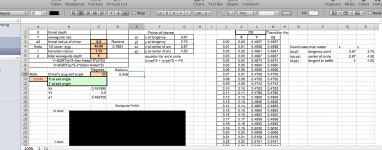
Referring to the spreadsheet by 'Josh K' (see attached) and using a BMS-4525 compression driver. This driver has a exit angle of 20 degrees:
1. The driver throat radius is .5 inches (its a 1"driver) however the spreadsheet yields a .4657 inch starting radius result. How can the starting radius be smaller than .5"? Is there a mistake in the spreadsheet formula?
2. Also in recent days I have seen a different formula posted as related to a smooth connection between the driver and OS waveguide. Here is the link to post 6053 in the Geddes on waveguides forum: http://www.diyaudio.com/forums/multi-way/103872-geddes-waveguides-606.html. I am having trouble understanding how this relates to the formula widely used, in most spreadsheets from Dr. Geddes: y(x) = sqrt(throat radius^2 + x^2 Tan(coverage_angle)^2)(x is the distance along the axis. Note that at x = 0 the angle is zero and the radius is "throat_radius")
3. Also, in the JoshK spreadsheet, there are two cells, C11 and C12 (X and Y at exit angle), I an confused abut their purpose / use in this spreadsheet.
Thank you!
- EqJive
I'm working a OS wave guide and have compared several of the worksheets from the forums. However, I am consistently gummed up on several points:
Referring to the spreadsheet by 'Josh K' (see attached) and using a BMS-4525 compression driver. This driver has a exit angle of 20 degrees:
1. The driver throat radius is .5 inches (its a 1"driver) however the spreadsheet yields a .4657 inch starting radius result. How can the starting radius be smaller than .5"? Is there a mistake in the spreadsheet formula?
2. Also in recent days I have seen a different formula posted as related to a smooth connection between the driver and OS waveguide. Here is the link to post 6053 in the Geddes on waveguides forum: http://www.diyaudio.com/forums/multi-way/103872-geddes-waveguides-606.html. I am having trouble understanding how this relates to the formula widely used, in most spreadsheets from Dr. Geddes: y(x) = sqrt(throat radius^2 + x^2 Tan(coverage_angle)^2)(x is the distance along the axis. Note that at x = 0 the angle is zero and the radius is "throat_radius")
3. Also, in the JoshK spreadsheet, there are two cells, C11 and C12 (X and Y at exit angle), I an confused abut their purpose / use in this spreadsheet.
Thank you!
- EqJive
Attachments
OSWG Solvent
JK's file has security issues. Use the attached Excel OSWG.zip file instead.
The smaller figure represents the y-intercept where the slope of the horn profile graph is 0 deg. This is not the point where you will be joining the horn to the compression driver, it is of mathematical interest only.
See the thumbnail included with the referenced post for the meaning of the variables used that are not sufucuently explained in the text.
Regards,
WHG
Hi,
I'm working a OS wave guide and have compared several of the worksheets from the forums. However, I am consistently gummed up on several points:
Referring to the spreadsheet by 'Josh K' (see attached) and using a BMS-4525 compression driver. This driver has a exit angle of 20 degrees:
JK's file has security issues. Use the attached Excel OSWG.zip file instead.
1. The driver throat radius is .5 inches (its a 1"driver) however the spreadsheet yields a .4657 inch starting radius result. How can the starting radius be smaller than .5"? Is there a mistake in the spreadsheet formula?
The smaller figure represents the y-intercept where the slope of the horn profile graph is 0 deg. This is not the point where you will be joining the horn to the compression driver, it is of mathematical interest only.
2. Also in recent days I have seen a different formula posted as related to a smooth connection between the driver and OS waveguide. Here is the link to post 6053 in the Geddes on waveguides forum: http://www.diyaudio.com/forums/multi-way/103872-geddes-waveguides-606.html. I am having trouble understanding how this relates to the formula widely used, in most spreadsheets from Dr. Geddes: y(x) = sqrt(throat radius^2 + x^2 Tan(coverage_angle)^2)(x is the distance along the axis. Note that at x = 0 the angle is zero and the radius is "throat_radius")
See the thumbnail included with the referenced post for the meaning of the variables used that are not sufucuently explained in the text.
3. Also, in the JoshK spreadsheet, there are two cells, C11 and C12 (X and Y at exit angle), I an confused abut their purpose / use in this spreadsheet.
Thank you!
- EqJive
Regards,
WHG
Attachments
Last edited:
Eqjive, have you made any progress on your Waveguide yet?
BMS 4525 does'nt exist as far as I know. You probably mean the 4524 ?
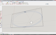
I am considering constructing a OSWG myself, preferably a hybrid /elliptical shape.
At this moment Iam playing with AutoCad and Solidworks, but here's an early attempt in SketchUp.
BMS 4525 does'nt exist as far as I know. You probably mean the 4524 ?
I am considering constructing a OSWG myself, preferably a hybrid /elliptical shape.
At this moment Iam playing with AutoCad and Solidworks, but here's an early attempt in SketchUp.
Attachments
Notes
1) Given a horn axis [z], note that the tangent point for the two hyperbole in the [x,z] and [y,z] plains must fall on a circle [r] in the [x,y] plain that represents the driver exit radius [r]. From there (a/b=1), all [x,y] sections will be ellipses, with changing aspect ratios [a/b > 1 < k], where [k] is the aspect ratio at the horn mouth.
2) For mouth treatment and construction notes see the tread:
http://www.diyaudio.com/forums/mult...iffraction-your-conical-horn.html#post3948677
Regards,
WHG
Last edited:
1) Given a horn axis [z], note that the tangent point for the two hyperbole in the [x,z] and [y,z] plains must fall on a circle [r] in the [x,y] plain that represents the driver exit radius [r]. From there (a/b=1), all [x,y] sections will be ellipses, with changing aspect ratios [a/b > 1 < k], where [k] is the aspect ratio at the horn mouth.
2) For mouth treatment and construction notes see the tread:
http://www.diyaudio.com/forums/mult...iffraction-your-conical-horn.html#post3948677
Regards,
WHG
Thanks for the citation!
- Status
- Not open for further replies.