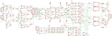
I took too long typing my previous attempt at this post, so you guys get the short version. The idea of this design is to be able to use multiple processors with different pickup selections. EG. Clean channel gets both pickups, distortion gets bridge pickup. I have been through several iterations of this design and decided to go back to the drawing board. The schematic is based off a jfet input stage, tl074 DI box, and 4066's as switchers. Top left circuit goes in the guitar, the rest is the control unit. Switches are controlled by 3.3v micro-controller. I am about to start bread-boarding and looking for thoughts. Any help is greatly appreciated!
Attachments

My first post here. This thread is over a week old with no replys so I'll give it a shot.
There seems to be a feedback resistor missing from IC3A. Hard to tell what all the switching does. What does IC4 do? The control lines for all but IC4A and IC4D are connected to the emitters of the 2N2222 transistors. That will never work. The control lines need to swing to atleast 12V so they need to go to the collectors to get the voltage swing. If you need a signal inversion, connect to the collector of the signal you want to invert with maybe a 10K resistor to the base of the next transistor. A 1K collector load on those transistors is pretty low. A 47K will work fine.
Have you tweeked those J201 buffers? 2.2K on the drain seems a little low.
Thanks Loudthud for the reply. I've been revising this project and I think I'm getting close.
First off, IC4 was an idea I had to put a virtual "phase" switch in. I removed it because I thought it would put the pickup out of phase with the other, but won't. It would have also inverted the pickup for both channels, not ideal. I decided to implement the phase switch with a simple inverter stage which didn't work either. I have an idea how to make this work but THAT's on the back burner.
Second, you caught my mistake in the transistor driver. I realized it the day after I posted. The whole driver has been removed from new schematic because the focus is on audio signal path.
Now on to the "missing" feedback resistor on IC3A. The real mistake was on 3D, corrected in new schematic as well. There is no feedback resistor because there is no input resistor. No gain, voltage follower. IC3A and 3B form a balanced line driver. Taken from
http://experimentalistsanonymous.com/diy/Schematics/Tone Control and EQs/Mixers and EQs.gif
And I have not tweaked the 201s. I will check that out and do the math. I bread-boarded it with 2.2k and it worked, didn't actually bias the transistor. I plan on building a FINAL version soon.
The new schematic is kind of confusing because I used a bunch of trim pots. SO>
R39,R43 will be removed.
R28, R30, R57, R58 are 4/6 of AD5206 6ch Digital pot.
R21, R7 final makeup trim *needs testing*
This schematic is in testing. Have not had much of a chance to play with the digipot volume settings / pickup blend other than verify 0 is quiet and 255 is loud. It sounds really good though. Clean and Warm. The bass is a slightly "loose" for my taste, so I plan on replacing Input caps with metal film and 10ufs with non-polarized. Might try 1uf NPs as well. Final will use metal film and poly caps as well metal film resistors.
The project has no user interface ATM, but I should be able to get that going in the next few weeks. I will be recording audio clips shortly. I recorded a few short clips with my guitar before installing the buffer. I THINK I remember which patches I used, lol.
Thanks again Loudthud,
Joe
Attachments
- Status
- Not open for further replies.