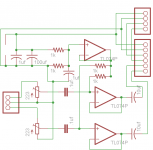
I'm not sure if this is the best place to post this, but here goes. I built a preamp for my guitar with the following circuit. My perfboard prototype is installed in my guitar and functions decently. Supply is 5v and I omitted the cap on the 1/2 V line. I plan on raising the supply voltage to 12 volts as revisions allow. Please keep in mind this is just the preamp for this project. I am revising the rest of the circuitry once again and taking a final look at the preamp before finalizing the design and possibly making smt board. Connection to the rest of the project is pin header to 50' of 6x 24awg, shielded conductor. Circuit SEEMS a bit noisy, although I'm sure the 12v supply will help, as will shielding of the electronics cavity in the guitar. Any thoughts, comments, suggestions are appreciated! If you are intrested in the REST of the project, email me cheeseburgerjoe@yahoo.com.
Attachments
Sorry, but that's absolutely horrible - you must not leave out the supply decoupling capacitor, and the resistors are all FAR too low a value.
You're feeding the pickups into a 1K input impedance when the gain is at maximum, which is going to reduce their output to almost nothing, and completely ruin their frequency response. 22K pots are also far too low, and will ruin the sound - use 470K or 1M pots.
Put the missing capacitor back in, change those two resistors to 47K, and change the input resistors to 470K or 1M.
I'm assuming a TL074 will even work off a single 5V supply?.
Nigel, thanks for the input. The tl074 does work off 5v. Not sure that I leaves much headroom for the signal. Will change trimmers to 1m. Are the two resistors your talking about are the input bias resistors? Is there a design that will sound better *after I make changes of course*
I have Toshiba 75064s and jrc 4558s, wondering if either of these would work better. Also thinking about using fets instead of opamps. Any thoughts?
I have Toshiba 75064s and jrc 4558s, wondering if either of these would work better. Also thinking about using fets instead of opamps. Any thoughts?
If you want to try a Fairly good sounding and clean Guitar pre I just finnished designing and building one that turned out pretty good ... It has plenty of Gain if you need it , a High Input impedance and Bass and Treble tone controlls and uses a dual opamp and if powered off of 9v (couple be powered at up to 32v + depending on the opamp ....
I also have a Pcb design if you want to try it .....
While it isn"t the best design (I"m not a designer) it does work pretty well and the PCB is small enough to actually fit in your guitar ....
Cheers
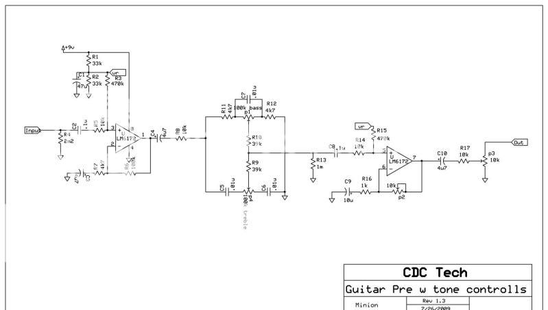
PS: excuse my crappy schematic writeing skills but this is actually the first schematic I have ever written ....
I also have a Pcb design if you want to try it .....
While it isn"t the best design (I"m not a designer) it does work pretty well and the PCB is small enough to actually fit in your guitar ....
Cheers
PS: excuse my crappy schematic writeing skills but this is actually the first schematic I have ever written ....
cheeseburgerjoe said:Nigel, thanks for the input. The tl074 does work off 5v. Not sure that I leaves much headroom for the signal. Will change trimmers to 1m. Are the two resistors your talking about are the input bias resistors?
Yes, they set the input impedance, which is currently FAR too low. Notice Minion's example uses a 470K.
Is there a design that will sound better *after I make changes of course*
It's only a buffer, and at a fairly high signal level, as long as you don't clip it, there shouldn't be much difference in the sound.
I have Toshiba 75064s and jrc 4558s, wondering if either of these would work better. Also thinking about using fets instead of opamps. Any thoughts?
The TL074 is a FET input amplifier, and a pretty decent choice.
Nigel, thanks for your input. I have revised my schematic with your suggestions. I was wondering if the buffered 1/2v makes much of an improvement over un-buffered. Also would it be better to buffer 1/2v with 2 op-amps, 1 for each signal in? Or is this just adding un-needed complexity? I figured the o74 would be a the best choice out of all the spare op-amps I have. For the final build I'm thinking about changing the op-amp *I plan on making a SMT as it is built into the guitar. Also, for the power supply I'm debating 12 or 15 dual supply. Any thoughts?
Minion, thanks for the schematic. I will have to play around with it when I get a chance!
Thanks again
Joe
Minion, thanks for the schematic. I will have to play around with it when I get a chance!
Thanks again
Joe
Attachments
Seems the best I can do on short notice is 100k trimmers. I'm thinking about connecting these in between 2 100k resistors. Maybe even a 200k on the high side and 100k to ground. Would 300k be acceptable?
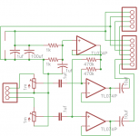
Well I have updated my schematic, with changes mentioned. Also included my bypass module, and will post a schematic of my *brain* first chance I get. Still haven't got my hands on any 1m trimmers, but tried using.... Signal in - 100k resistor - 100k pot - 100k Resistor - Gnd. Was not able to adjust the signal down enough, After making the changes mentioned I was unable to tell any difference. I am apparently clipping the o74, considering that I'm still using 5v supply, that might be the problem. I need to finish my 15v dual supply, will try to wrap that up in the next couple days.
Attachments
cheeseburgerjoe said:Still haven't got my hands on any 1m trimmers, but tried using.... Signal in - 100k resistor - 100k pot - 100k Resistor - Gnd. Was not able to adjust the signal down enough,
With the trimmers wired as shown, you can't fail to turn it down enough, they are simple attenuators, and will reduce the signal completely to zero - they don't alter the gain at all, just the input signal from maximum down to nothing.
Just noticed you've got an extra 100K in the bottom end, take that out and fit a wire - it's stopping the trimmer doing anything.
I will try shorting the bottom 100k resistors. Should 200k be sufficient? I finished the schematic for the brain module I've prototyped *I know, I know, schematic THEN prototype, lol* so here's a copy of that.
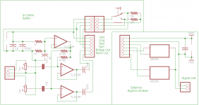
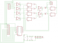
I realize that with the current design the brain is not biased to 1/2v *I added the output bypassing caps to the on board preamp, and have made no changes to the brain yet. I WAS going to change schematic for 15v dual supply *guitar pre will be running single supply still.* But instead, I've decided to re-design the brain using ad5206 *6ch digital pot* instead of 4066s. The problem here being that the 5206 is 5v. Still pondering the best way to make this work. Here's a schematic for the brain, the bypass module is for testing purposes only. I have ommited the BS2 from schematic, nothing complicated here. The 12pin feeds 5v to bs2, the other 9 wires are pin to pin connection. I will be making ANOTHER schematic for the bs2 board in the next couple days.
Thanks again for all your help
Joe
Attachments
cheeseburgerjoe said:I will try shorting the bottom 100k resistors. Should 200k be sufficient?
It's better than having 100K's in the bottom of the pots, but 200K is probably more loading than the pickups are designed for.
I finished the schematic for the brain module I've prototyped *I know, I know, schematic THEN prototype, lol* so here's a copy of that.
I realize that with the current design the brain is not biased to 1/2v *I added the output bypassing caps to the on board preamp, and have made no changes to the brain yet. I WAS going to change schematic for 15v dual supply *guitar pre will be running single supply still.* But instead, I've decided to re-design the brain using ad5206 *6ch digital pot* instead of 4066s. The problem here being that the 5206 is 5v. Still pondering the best way to make this work. Here's a schematic for the brain, the bypass module is for testing purposes only. I have ommited the BS2 from schematic, nothing complicated here. The 12pin feeds 5v to bs2, the other 9 wires are pin to pin connection. I will be making ANOTHER schematic for the bs2 board in the next couple days.
It's all getting very complicated 😀
BTW, instead of using opamp buffers from the pickups, have you considered simple FET source followers?.
I just revised my schematic. I'm trying the KISS method. Any thoughts Nigel? I'm also wondering what I should do with my power supply? I'm probably going to use the one from my Kawai K3m. It's +12v- +5v and I don't plan on using the -12v right now. Is it ok to leave the output unconnected?
Attachments
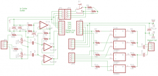
cheeseburgerjoe said:I just revised my schematic. I'm trying the KISS method. Any thoughts Nigel?
Looking better, but you are making a substantial loss through the input attenuator.
I'm also wondering what I should do with my power supply? I'm probably going to use the one from my Kawai K3m. It's +12v- +5v and I don't plan on using the -12v right now. Is it ok to leave the output unconnected?
I would expect using just the 12V positive should be fine.
I guess I'm still doing something wrong. I built the new version and I get no output. When I turn the power off, it works for a second. I'm thinking I need to move the summing resistors after caps. I've only had a little while to test for mistakes.
Should I be using op amps to buffer the output or should I be ok without them. Also I'm thinking about making the pickup switch output to one wire. Simple voltage divider setup to make the on - on - on switch output gnd - 6v - 12v. Is there an easy way to decode this on the other end?
Should I be using op amps to buffer the output or should I be ok without them. Also I'm thinking about making the pickup switch output to one wire. Simple voltage divider setup to make the on - on - on switch output gnd - 6v - 12v. Is there an easy way to decode this on the other end?
- Status
- Not open for further replies.
- Home
- Live Sound
- Instruments and Amps
- Guitar Pre Revisions?