Hello All,
I've been hung up recently on building a guitar stand alone power amp to keep around the house. I love my Soldano SLO, and thought I'd simply build the power amp section of that (master volume forward). However, randomly, I listened to an interview with Mr. Soldano, where he mentioned that he added a gain/driver stage to the front end of his rack power amp to drive it properly. This has thrown me for a loop, and I'm hoping you can all help me out with a couple questions.
Why is this first/driver stage really needed? Reviewing the entire SLO schematic, the FX return goes directly into a cathode follower with approximately unity gain and low impedance to drive the tone stack. From there it goes to the master volume and into the phase splitter. Am I assuming wrong that the signal a stand alone power amp would receive is the same to what is coming through an FX loop? If there is unity gain in this stage and no tone stack to drive in the power amp, then why is it needed?
From there I started reviewing other power amp schematics (AX84 & Mesa 50:50) and see that they as well have a driver stage before the phase splitter. Most of which are single gain stages, and the same with any hifi amp. Any insight will be great to what I can calculate out and figure what is required of this stage. I've been reading some intro's to tube design, but I'm just getting started and need a little direction.
Thanks in advance for any help,
Jason
Attachments
You're traveling on the road to a better guitar amplifier. Guitar amplifiers are exemplified by having very high input sensitivity, and the ability to overamplify the guitar's pickup's waveforms well past the point of clipping. Distortion, anathema to an audiophile amp, is not just desired, but designed-in for a guitar amp.
Thing is, it is not easy to nail down how best to do this within a preamplifier stage, such as you are contemplating.
Conventionally, in the more renowned (and dâhmned expensive!) all-in-one-box guitar amplifiers, having chained power-supply taps with the barest minimum voltages passing thru is key to sub-second-to-many-seconds nonlinear distortion effects. Likewise, having high amplification near (but not exactly at ) the front end, key.
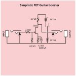
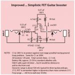
The first diagram is fine, but simplistic, and not terribly likely to do more than JUST amplify the guitar's output by 20× or so. Plenty to drive the amplifier. If your amp is quite linear, then you'll get low distortion effects, and a quite clean reproduction.
Is that what you are shooting for?
Otherwise, taking a different approach, with 3+ stages of starved-anode amplification, both back-to-back Zener and criss-crossed germanium diodes in the line, switchable of course, is the way to really kick up the often-musically-interesting distortion BEFORE amplification.
Again, what is your goal?
For the absolute least-trouble, you also could settle on a single FET powered by an 18 V battery (2 9V cells in series). Or, for that matter, you could purchase an EFX soap-bar box and feed the guitar straight into that. The output will definitely be 'strong enough' for input-to-the-amplifier.
The FET amp approach results in a NOT-distorted amplification of the guitar output, normally.
And it is compact.
And very, very low power.
A set of batteries will last maybe 50 hours.
As in this…
Thing is, it is not easy to nail down how best to do this within a preamplifier stage, such as you are contemplating.
Conventionally, in the more renowned (and dâhmned expensive!) all-in-one-box guitar amplifiers, having chained power-supply taps with the barest minimum voltages passing thru is key to sub-second-to-many-seconds nonlinear distortion effects. Likewise, having high amplification near (but not exactly at ) the front end, key.
The first diagram is fine, but simplistic, and not terribly likely to do more than JUST amplify the guitar's output by 20× or so. Plenty to drive the amplifier. If your amp is quite linear, then you'll get low distortion effects, and a quite clean reproduction.
Is that what you are shooting for?
Otherwise, taking a different approach, with 3+ stages of starved-anode amplification, both back-to-back Zener and criss-crossed germanium diodes in the line, switchable of course, is the way to really kick up the often-musically-interesting distortion BEFORE amplification.
Again, what is your goal?
For the absolute least-trouble, you also could settle on a single FET powered by an 18 V battery (2 9V cells in series). Or, for that matter, you could purchase an EFX soap-bar box and feed the guitar straight into that. The output will definitely be 'strong enough' for input-to-the-amplifier.
The FET amp approach results in a NOT-distorted amplification of the guitar output, normally.
And it is compact.
And very, very low power.
A set of batteries will last maybe 50 hours.
As in this…
Attachments
Goat,
Thank you for the prompt/thorough reply!
The goal is to simply recreate only the power section of the SLO amp and make it usable with a wide variety of pre-amplifiers and effects. I would assume since Mr. Soldano has always said that a hifi'ish power section was his goal, then linearity is the direction.
Mathematically speaking, with linearity in mind, what should be the objective of the first stage considering the following master volume/phase splitter sections that follow? Should I simply calculate the input sensitivity of the phase splitter and produce a gain stage that mimics what the pre-amp of the the SLO would normally produce?
Also, what is a safe input voltage to anticipate from external pre-amplifiers and effects?
Jason
Attachments
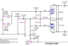
Reading your first comment again, and the one you just posted, I think I got it: you are trying to recreate the right-half of the SLO amplifier you already enjoy, to place in a standalone crate, for home use. And you're continuing to wonder why you also probably need a front-end amplification stage before the phase-inverter/splitter section.
Right?
If that's right, it is simple: one cannot expect that of the very wide possibilities of sources (instruments, etc) that will be plugged into the amplifier, that they'll all dutifully stay within the “sweet spot” of input voltage levels. I, being a musician-cum-EECS-cum-physics goat, have seen VRMS (kind of 'average') guitar pickups from below 50 millivolts to well over 1,000 millivolts. More modern guitar kit often have internal preamplifiers (often called 'direct boxes') which kick up dozens-of-millivolts of pickup output to well over 2,500 mVRMS. Likewise, I've encountered EFX boxen that suppress relatively large input signals down to handfuls of millivolts at output, or exactly the opposite: way up in the 1,000 to 4,000 mV output range.
Thing is, a long-term-generally-useful amplifier needs to handle all these ranges. It also needs to offer high input impedance to the device clicked into the input jack. It might be a conventional unadorned magnetic pickup (low impedance, but also low output), or it might be something exotic like a piezo pickup (very high impedance, but often decent output). Who knows?
The front end stage, especially when designed to acceptably take 3,000+ mV input without distorting its amplified output signal … followed by a audio-taper pot to 'tame' the amplification to something more appropriate for the rest of the amplifier's internal design, is the bog standard way to get the job done.
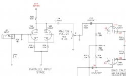
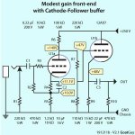
For this reason, I think your desire to implement a bit of a franken-amp is … a wee bit misguided. However, if the power supply for your franken-amp has a modest voltage output (i.e. somewhere between 20 and 30 V DC, well regulated and filtered!), then you could implement the JFET 'front end' internally, as shown in diagram № 2 above. Or, if you just have 'hundreds of volts', then use a 12AX7 or similar as the gain element. Larger anode resistor than the JFET, but surprisingly, the same cathode/source resistor and capacitor.
JFETS in almost every way emulate pentode transconductance curves. And pentodes are sweet input elements for quality instrument amplifiers.
Just Saying,
GoatGuy ✓
Right?
If that's right, it is simple: one cannot expect that of the very wide possibilities of sources (instruments, etc) that will be plugged into the amplifier, that they'll all dutifully stay within the “sweet spot” of input voltage levels. I, being a musician-cum-EECS-cum-physics goat, have seen VRMS (kind of 'average') guitar pickups from below 50 millivolts to well over 1,000 millivolts. More modern guitar kit often have internal preamplifiers (often called 'direct boxes') which kick up dozens-of-millivolts of pickup output to well over 2,500 mVRMS. Likewise, I've encountered EFX boxen that suppress relatively large input signals down to handfuls of millivolts at output, or exactly the opposite: way up in the 1,000 to 4,000 mV output range.
Thing is, a long-term-generally-useful amplifier needs to handle all these ranges. It also needs to offer high input impedance to the device clicked into the input jack. It might be a conventional unadorned magnetic pickup (low impedance, but also low output), or it might be something exotic like a piezo pickup (very high impedance, but often decent output). Who knows?
The front end stage, especially when designed to acceptably take 3,000+ mV input without distorting its amplified output signal … followed by a audio-taper pot to 'tame' the amplification to something more appropriate for the rest of the amplifier's internal design, is the bog standard way to get the job done.
For this reason, I think your desire to implement a bit of a franken-amp is … a wee bit misguided. However, if the power supply for your franken-amp has a modest voltage output (i.e. somewhere between 20 and 30 V DC, well regulated and filtered!), then you could implement the JFET 'front end' internally, as shown in diagram № 2 above. Or, if you just have 'hundreds of volts', then use a 12AX7 or similar as the gain element. Larger anode resistor than the JFET, but surprisingly, the same cathode/source resistor and capacitor.
JFETS in almost every way emulate pentode transconductance curves. And pentodes are sweet input elements for quality instrument amplifiers.
Just Saying,
GoatGuy ✓
For a detailed stage by stage analysis of the SLO100, you GOTTA READ THIS!
Soldano Super Lead Overdrive Channel Circuit Analysis
There is a lot more real engineering going on in this amp than the usual copy a FMV, then tweak "design."
Soldano Super Lead Overdrive Channel Circuit Analysis
There is a lot more real engineering going on in this amp than the usual copy a FMV, then tweak "design."
Tubelab,
Thanks for the link! Funny you post that here, as I caught that analysis about a year ago, liked the article, and picked up all four of his books. Slowly working my way through them, so I understand the concepts, just not how to actually implement them effectively in situations. Also, unfortunately, the analysis stops at the FX return stage and doesn't completely break down how it drives the phase inverter.
GoatGuy,
You nailed it, I have my assignment now to design the first 12ax7 stage to simply handle a 3,000 mV input cleanly. Then feed it into the master volume and copy the rest of the power section. Thank you for the help.
Addition, is it worth my while to look into a parallel input stage? I've read where it thickens the sound a little bit, but have never heard one before. Curious if it's worth the effort since the spare side of the 12ax7 will be sitting there unused.
Thanks,
Jason
I caught that analysis about a year ago, liked the article, and picked up all four of his books.
Someone posted the link somewhere on this forum a few weeks ago. I looked at it then, bookmarked the link, then forgot about it. After you posted this I went back to the link and reread it....then ordered the simulation book.
I have been building guitar amps since I was 8 years old, so I understand them pretty well. Ditto germanium fuzz boxes. The HiFi stuff came later.
I was an electronics design engineer at Motorola for most of my 41 year career, so I am familiar with simulation and LT spice.
The book hints that some methods of simulation will be presented for intentionally distorting a signal such that the results will be musically pleasing.....OK, I'm interested enough to drop $30.
...a guitar stand alone power amp to keep around the house. ...
A power amp won't play guitar.
I would NOT! want an SLO100 power stage as a house pet. (Even living here in the woods, it is TOO DARN LOUD.)
What you want is the *preamp* from guitar jack to that last jack before the power stage.
Then I would steal the last bit of an AA Champ or Epi Jr: 1/2 12AX7 and a 6V6/EL84. You can flog a 5-Watt amp in the home without cracking teeth or plaster. The SLO's complex *preamp* does most of the sound-shaping.
BTW, the SLO FX return has significant gain before the cathode follower.
You nailed it, I have my assignment now to design the first 12ax7 stage to simply handle a 3,000 mV input cleanly.
That's impossible with a grounded cathode 12 AX7, unless you provide NFB to the 1st stage cathode!
Best regards!
A power amp won't play guitar.
I would NOT! want an SLO100 power stage as a house pet. (Even living here in the woods, it is TOO DARN LOUD.)
What you want is the *preamp* from guitar jack to that last jack before the power stage.
Then I would steal the last bit of an AA Champ or Epi Jr: 1/2 12AX7 and a 6V6/EL84. You can flog a 5-Watt amp in the home without cracking teeth or plaster. The SLO's complex *preamp* does most of the sound-shaping.
BTW, the SLO FX return has significant gain before the cathode follower.
Quite the opposite! The only place I don't get told to turn it down is my house. Open up the garage in the summer and let it fly. To each his own though.
That's impossible with a grounded cathode 12 AX7, unless you provide NFB to the 1st stage cathode!
Best regards!
Thanks for your input. Haven't had a chance to sit down and crunch the numbers yet, so going on your word here. Plus I'm new to this... What parameters do you believe is the ideal situation for the first stage? With that, what tube stage would you build considering the power section in hand?
Jason
The SLO power section needs about 2V to reach full output. Since not all preamp or pedals can provide that, a extra gain stage is convinient.
I would use a large cathode resistor to withstand large input signals. E. g. 2k2 // 47uF, and a 100k anode. Add a 10K grid resistor and you are good to go 😀
I would use a large cathode resistor to withstand large input signals. E. g. 2k2 // 47uF, and a 100k anode. Add a 10K grid resistor and you are good to go 😀
Thanks for this schematics, GoatGuy!
But this ain't no real grounded cathode design, and my objections weren't against the possible gain.
Best regards!
But this ain't no real grounded cathode design, and my objections weren't against the possible gain.
Best regards!
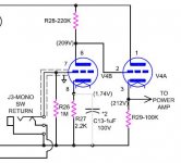
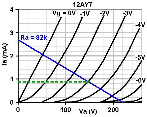
Rk = 15k, 48 V on the cathode, ergo roughly 3 mA through a half-12AX7 with only 200 volts between anode and cathode. That puts Vgk at about (-0.6 V), well into grid current.Perhaps as this, answering the ''can't do that much gain with a 12AX7 stage!'' objection. GoatGuy
The output signal can swing negative by up to 50 volts more or less, but can barely swing positive at all. Positive signal peaks will be heavily clipped and rounded-off. There will be lots of harmonic distortion in the output.
Did you intend the 12AX7 to be biased into extremely non-linear operation, a la Leo Fender's accidental Bassman design?
While this (Goatguy's) approach keeps heater-cathode voltage down to about 50V rather than 200 V, which is good for the heater insulation, it also increases anode dissipation of the cathode-follower stage considerably. Vak = 200V and Ik = 3 mA means 600 mW of quiescent anode dissipation, which is pushing a half-12AX7 much harder than usual, about three times as hard as the typical Fender/RCA gain stage with Ik=1mA and Vak=200V or so.
-Gnobuddy
12AX7
Can use a 12AY7, 12AT7, instead.
Or put a buffer before the 12AX7 (opamp) and bias the grid at 1V and the opamp will supply current when the grid goes positive.
Can use a 12AY7, 12AT7, instead.
Or put a buffer before the 12AX7 (opamp) and bias the grid at 1V and the opamp will supply current when the grid goes positive.
R9 is 15k in Goatguy's schematic. Not Leo's 100k (the value you showed in your image), but nearly seven times smaller.
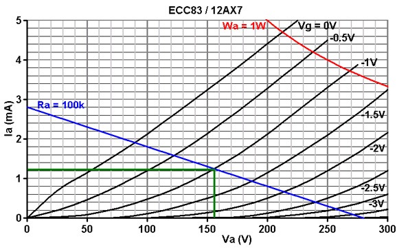
Try drawing a 15k load-line on the 12AX7 curves, with B+=250V and Vak=200V, and you'll see what I mean! 🙂
-Gnobuddy
Try drawing a 15k load-line on the 12AX7 curves, with B+=250V and Vak=200V, and you'll see what I mean! 🙂
-Gnobuddy
R9 is 15k in Goatguy's schematic. Not Leo's 100k (the value you showed in your image), but nearly seven times smaller. Try drawing a 15k load-line on the 12AX7 curves, with B+ = 250V and VAK = 200V, and you'll see what I mean! 🙂
and…There will be lots of harmonic distortion in the output.
-Gnobuddy
😉 it is, after all, a guitar amplifier … -= GoatGuy ✓ =-
That's why I asked if it was intentional on your part. 🙂😉 it is, after all, a guitar amplifier … -= GoatGuy ✓ =-
Have you listened to your circuit? I'm curious if the huge reduction in cathode-follower load changes the timbre (harmonic spectrum) of the distortion significantly, as compared to the Bassman and its derivatives.
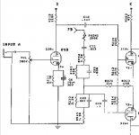
As it happens, I too have been thinking about the direct-coupled cathode follower stage for use in a guitar preamp I'm pondering, and in particular, I've been wondering how to reduce that huge DC voltage between cathode and heater that fries heater-cathode insulation.
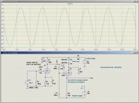
My (untried, never been built, only simulated) solution is attached. I used a resistive voltage divider between common-cathode and cathode-follower stages, just as you did. But I added a negative supply voltage rail, and returned both the divider and the CF stage's cathode resistor to this, rather than to ground (0 V).
The final piece of the puzzle is dropping about 180 - 200 V in the anode supply to the CF stage, so that its Vak is about the same as in the Bassman et al.
With DC operating conditions for the CF virtually unchanged from the Bassman / Marshall classic amps, I was able to use a more normal sized cathode resistor, rather than lowering it to an extreme. In this particular simulation, I used 68k. The simulation behaves similarly with 100k and 82k as well.
The reason I immediately understood what your design was supposed to do was that I had already been thinking about the same problem, looking for solutions. 🙂
-Gnobuddy
Attachments
- Home
- Live Sound
- Instruments and Amps
- Guitar Power Amp - First Stage