In order to know if the 072 is the problem or not, you have to pull the 4066 out of the circuit. Probing the circuit before the 4066 is not good enough.
What is likely happening, is the bottom half of the output is essentially being shorted to ground through protection diodes on the 4066 input. So you need to remove the 4066 completely in order to see if the clipping is from the 072 or the 4066.
wow! you are absolutely right! as soon as i pull it out the signal is fine!

thank you so much for that!!!
so..... i should figure out how to AC couple the signal, or how to power the 4066 with a dual supply... i guess that will be problematic since the 4066 can only handle 18v at most, and im using +-15v for the TL072. any ideas on that?
Dude! If you want help, you need to be a little more specific. Showing us incorrect or misleading schematics makes things a lot harder. Can you show us an actual schematic of the circuit you got that waveform from?
Mike
hey mike, - im very sorry if i seemed unclear, since i really appreciate your help. i believe i did post a complete op amp schematic though - posting the complete thing encompassing everything the instrument does would be very confusing.
wow! you are absolutely right! as soon as i pull it out the signal is fine!
thank you so much for that!!!
so..... i should figure out how to AC couple the signal, or how to power the 4066 with a dual supply... i guess that will be problematic since the 4066 can only handle 18v at most, and im using +-15v for the TL072. any ideas on that?
ugh... using a dual supply for the CMOS switch i believe means i need to adjust my logic gate to pull down to the minus voltage rather than to 0v. is this correct? i haven't really used CMOS switches much before....
and thanks again guys, you rock
Well I can suggest 2 things:
1) run the 4066 off +/-15V, but install 100 Ohm resistors in series with each supply to the 4066. I have done this before and it seems to work. It might be risky so don't blame me if your 4066 overheats or doesn't work properly. Like I said, I have used this method before and it worked for me.
2) You can try a 1uF output cap from the opamp going to the junction of two 47k Ohm resistors, one connected to +15V, and the other ground. Then use a cap on the output of the 4066 as well to the next stage.
Well I can suggest 2 things:
1) run the 4066 off +/-15V, but install 100 Ohm resistors in series with each supply to the 4066. I have done this before and it seems to work. It might be risky so don't blame me if your 4066 overheats or doesn't work properly. Like I said, I have used this method before and it worked for me.
2) You can try a 1uF output cap from the opamp going to the junction of two 47k Ohm resistors, one connected to +15V, and the other ground. Then use a cap on the output of the 4066 as well to the next stage.
the latter sounds like a great solution - thank you so much - i will try it right now and report back...
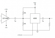

Something like this...
okay... i tried this - and it fried my chip! lucky i have a dozen
maybe its because i didn't do anything similar to the phase switch gate... ill try that now and report back... negative 1uF cap lead to cmos, right?
thanks!!!
If you are using polarized (electrolytic) caps, the +'ve lead should go the the CMOS input where the resistors are.
It would be a lot easier if you used a bipolar supply on the 4066. It would be easy enough to change you logic transistors to switch from -15 to +15, don't you think?
Anyway, I'm calling it a night.. Good luck.
It would be a lot easier if you used a bipolar supply on the 4066. It would be easy enough to change you logic transistors to switch from -15 to +15, don't you think?
Anyway, I'm calling it a night.. Good luck.
If you are using polarized (electrolytic) caps, the +'ve lead should go the the CMOS input where the resistors are.
It would be a lot easier if you used a bipolar supply on the 4066. It would be easy enough to change you logic transistors to switch from -15 to +15, don't you think?
Anyway, I'm calling it a night.. Good luck.
i guess you are right... i might just do that... thank you so much for your help - i've learned a lot... i'm calling it a day as well... for now... later!
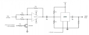
I just tried using a transistor to perform the phase switching, and it works pretty good, at least in the sim. Only thing is you need to drive the transistor with +15V and -15V, not just 0V and +15V.
This eliminates the need for a 4066 and its associated problems on a single supply, at least for the phase switching. It's something you could try anyway.
This eliminates the need for a 4066 and its associated problems on a single supply, at least for the phase switching. It's something you could try anyway.
Attachments
i need to be able to flip the phase of all pickups at the same time using a logic signal
dataplex, maybe I'm a little obtuse, but I just don't see how flipping the phase of ALL of the coils simultaneously will do anything at all to the sound. To get any effect at all at least one of the multiple pickups must be out of phase with the others.
Mike
dataplex, maybe I'm a little obtuse, but I just don't see how flipping the phase of ALL of the coils simultaneously will do anything at all to the sound. To get any effect at all at least one of the multiple pickups must be out of phase with the others.
Mike
no worries! so the idea is to flip the phase of the pickup coil just like you would do on a commercial ebow (ebows have a slide switch that allows you to chose between 0 degrees and 180 degrees) if the pickup is in phase with the driver coil, the string vibration will settle on the fundamental frequency - if the pickup is 180 degrees out of phase with the driver coil, the string will settle on the second or third harmonic of the fundamental frequency.
that way i can effectively expand the instruments range by switching the phase on all pickups with one switch.
I just tried using a transistor to perform the phase switching, and it works pretty good, at least in the sim. Only thing is you need to drive the transistor with +15V and -15V, not just 0V and +15V.
This eliminates the need for a 4066 and its associated problems on a single supply, at least for the phase switching. It's something you could try anyway.
that looks very cool! could be exactly what i am looking for...
one thought
as i mentioned earlier one of the new functions of this instrument allows you to pass any desired audio signal through the strings via the poweramps (like the the chet baker example i posted last night)
so whenever i connect an external input to the power amps (from your audio interface or whatever) i need the pickups to be bypassed, so that they don't interfere with the auxiliary input exciting the strings.
one of the perks of having the 4066 is that one chip would allow me to both flip the phase AND bypass the pickups when an auxiliary input is connected. so i would need to add another switch on the output of the second op-amp to bypass the pickup-coils going to the power amp - would perhaps a bypass transistor switch similar to the one you suggest for the phase switching distort the sound much? it'd be great if i can use transistors in both instances !
one of the perks of having the 4066 is that one chip would allow me to both flip the phase AND bypass the pickups when an auxiliary input is connected. so i would need to add another switch on the output of the second op-amp to bypass the pickup-coils going to the power amp - would perhaps a bypass transistor switch similar to the one you suggest for the phase switching distort the sound much? it'd be great if i can use transistors in both instances !
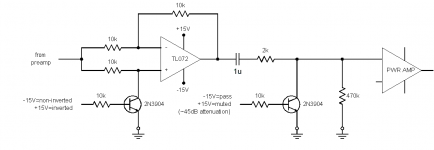
Yes, it will work to a degree. The following circuit provides about 45dB of attenuation going into the pwr amp, which is pretty good, but the 4066 would probably do 20dB better I would guess. 45dB attenuation means if you had 2V on the output of the TL072, about 12mV would still go into the pwr amp. Other than the limited attenuation, it does seem to work.
Attachments
Actually, the +'ve input of the op-amp sees the full output voltage of the previous preamp stage, not 50%.Looking at the phase switch, the cd4066 only switches 50% level.
Last edited:
- Status
- This old topic is closed. If you want to reopen this topic, contact a moderator using the "Report Post" button.
- Home
- Amplifiers
- Chip Amps
- guitar pickup pre / phase flipper