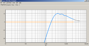
The very same measurement now with cursor.
thats a very nice result in rew to be honest FR response at least. most of the measurements look like alps in my rew, while in holm they look pretty ok 🙂
it does seems wheird there is not increase of spl towards 20khz. this should be even at 20 cm
I should first say that the tweeter is under digital frequency correction, not only a 4th order HP filter. I will post raw driver measurements. But only like 1 dB corrections.
The dimensions are 40mm wide, 20mm gap, 175mm high (but mounting at foot will add something to that) and depth is 22mm.
What can make 46mm out of that... or 23... ??
Actually, 175/4=43.... some physical experiments with small baffles to be conducted.
//
The dimensions are 40mm wide, 20mm gap, 175mm high (but mounting at foot will add something to that) and depth is 22mm.
What can make 46mm out of that... or 23... ??
Actually, 175/4=43.... some physical experiments with small baffles to be conducted.
//
thats a very nice result in rew to be honest FR response at least. most of the measurements look like alps in my rew, while in holm they look pretty ok 🙂
it does seems wheird there is not increase of spl towards 20khz. this should be even at 20 cm
Yes it should. The slight slope towards higher frequency is an intended "house curve". But the cut off is not. Will look into that. Actually the width sets the dipole frequency to something like 6-8khz so above that it will flatten out (I think).
//
Is it +10 dB?
I don't know if it is applicable to your DSP, but as a general rule it is not so good to have positive compensation as it could cause internal digital clipping.
I don't know if it is applicable to your DSP, but as a general rule it is not so good to have positive compensation as it could cause internal digital clipping.
Good point again solhaga - need to check this (again) also. I have a gain structure issue as a run the ribbon via a 2 ohm resistor. There is a 20 dB difference in the system unfortunately.
//
//
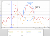
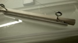
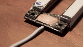
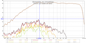
Dug into the distances and distorsions. The thing is of course a tuning fork. Its obvious just looking at it 🙂 The width corresponds to too high frequencies to be the cause. But magnets being 150mm corresponding to 2266 Hz and half length -> 4520Hz is spot on.
The 2940 Hz (112/56mm) is a mystery.
//
The 2940 Hz (112/56mm) is a mystery.
//
Attachments
Last edited:
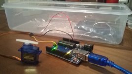
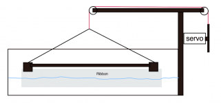
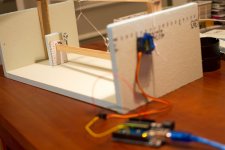
Building me an Arduino controlled ribbon etching machine. It will elevate the aluminum foil out of the NaOh bath so that a suitable thickness over the width can be obtained. It will have to be made in 2 runs starting form being half submerged and lifted out by the servo and manually turned around and repeated for the other side.
Attachments

Last edited:
That's very ingenious of you. Again, why not measure the resistance with the Arduino?Building me an Arduino controlled ribbon etching machine. It will elevate the aluminum foil out of the NaOh bath so that a suitable thickness over the width can be obtained. It will have to be made in 2 runs starting form being half submerged and lifted out by the servo and manually turned around and repeated for the other side.
Then you'll know exactly when to pull it out of the bath.
Yea that would be really cool. But its quite advanced. Need a measurement bridge etc. And its hard to make good connection to aluminium... I'll first try the raw basic time controlled variant 😉 The goal is to make the terassed ribbon as proposed in post #2 by waiting, lifting a bit, waiting, lifting a bit asf.
//
//
I don't know about NaOH as etchant, but when I have used HCl one problem is that the process heats up the bath and thus accelerates the etching.
So just rely on time is not exact enough. And then there the problem to get an exact concentration.
The easiest way to make the bridge resistors is to use cut out aluminium strips.
But as you said, your method is probably good enough.
So just rely on time is not exact enough. And then there the problem to get an exact concentration.
The easiest way to make the bridge resistors is to use cut out aluminium strips.
But as you said, your method is probably good enough.
Building me an Arduino controlled ribbon etching machine. It will elevate the aluminum foil out of the NaOh bath so that a suitable thickness over the width can be obtained. It will have to be made in 2 runs starting form being half submerged and lifted out by the servo and manually turned around and repeated for the other side.
hmm what is that image on the right? some sort of program to get a good overview of the actions ? i like it. i got an arduino myself to experiment with but im kinda noob with it , so far 🙂
I don't know about NaOH as etchant, but when I have used HCl one problem is that the process heats up the bath and thus accelerates the etching.
So just rely on time is not exact enough. And then there the problem to get an exact concentration.
The easiest way to make the bridge resistors is to use cut out aluminium strips.
But as you said, your method is probably good enough.
NaOh is quite slow, don't smell and no heat really. Takes 30 minutes to get form 15 to 8 um using ordinary "kaustiksoda".
//
Aha, then it is not so critical.NaOh is quite slow, don't smell and no heat really. Takes 30 minutes to get from 15 to 8 um using ordinary "kaustiksoda".
//
And when you are done you can use the caustic soda to clean the plumbing.
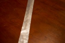
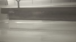
Took a first controlled bath 🙂
Also taking the chance to make some improvement to the connections on the driver. I hope to test this one today. Etching went well in the sense that the TNT Ribbonetcher-2 did perform well 🙂 In the 3rd picture one see the last phase where just 2 mm of the edge is etched.
//
Also taking the chance to make some improvement to the connections on the driver. I hope to test this one today. Etching went well in the sense that the TNT Ribbonetcher-2 did perform well 🙂 In the 3rd picture one see the last phase where just 2 mm of the edge is etched.
//
Attachments


Last edited:
Took a first controlled bath 🙂
Also taking the chance to make some improvement to the connections on the driver. I hope to test this one today. Etching went well in the sense that the TNT Ribbonetcher-2 did perform well 🙂 In the 3rd picture one see the last phase where just 2 mm of the edge is etched.
//
Nice to see you making progress!
For improved contact I can recommend Vandenhul 'The Solution', it also makes positioning the ribbon much easier.
regards,
Gerrit
Thanks! A lot to learn. Real progress sits in distortion measures. A lot of fail I predict. But great fun.
//
//
Measurement of the last ribbon. Given that it is no corrugation and at 15dB higher level than the previous measurement presented this is a step in the right direction I believe. Distortion looks also more "well behaved". Maybe the difference is due to assembly. Still, doing the DC movement check after final assembly it was not as good as when I adjusted it and decided to "seal the deal". So I need to introduce an adjustment mekanism in one end of the ribbon so that after the driver is assembled one can do vey fine tuning of its position. Its probable enough with making the piece that holds 1 of the ends of ribbon rotatable in the ribbon (z) plane. So some way to go still. But every time I hook in the ribbon its like a revelation in despite (thanks to????) the distortion.... we will see...
Just updating my "build log"... nothing to see here.... 🙂
Just updating my "build log"... nothing to see here.... 🙂
Attachments


- Status
- Not open for further replies.
- Home
- Loudspeakers
- Planars & Exotics
- Guillotine - son of Geriitts reductio ad minimum ribbon