Hi,
in the past two years I've harvested a bunch of power transformers from some cheesiy sounding and crappy Hammond transistor organs. Sadly, I didn't have a close look at their badges and the power consumption that might have been written there, but anyway, all these organs featured Leslie or Rotosonic units whose motors are of unknown power consumption as well.
The 1st pic shows a pair of identical trannies, Hammond part # 003-054471, coming from a Collonnade and a - smaller - Aurora Classic. Their lamination stacks measure 105 x 87 x 55 mm (4 1/8 x 3½ x 2 1/4 "):

Next one is the tranny of a notably bigger Concorde. Part # 003-046819. Lamination outline is the same, but stack height is a bit lower: 105 x 87 x 50 mm (4 1/8 x 3½ x 2 "):

Next one came form a Model 8022 organ. Part # 003-048011. Laminations measure 95 x 80 x 50 mm (3 3/4 x 3 1/8 x 2 "):

The next pair also was in the Colonnade and Aurora organs. Their primaries are 115 Vac, secondary is 14 Vac. Perhaps they might serve in a BTL pair (2 x 2) of amplifiers. Part # 003-054853, laminations are 76 x 63 x 41 mm (3 x 2 1/2 x 1 5/8 "):

The smallest one. Part # 003-046374, laminations are 66 x 56 x 26 mm (2 5/8 x 2 3/16 x 1 "):

Finally a 117 Vac power tranny that came from a Leslie 121 multi channel amplifier. It powered four almost identical amplifiers, consisting of a 12AU7 and a pair of fix biased 7189's each. This is the one I was referring to in my proper winding technique thread. I'm planning to rewind it as an OT of about 40 W power. Laminations are 114 x 95 x 33 mm (4½ x 3 3/4 x 1 1/4 "):

Which power capabilities can I expect from these transformers?
Best regards!
in the past two years I've harvested a bunch of power transformers from some cheesiy sounding and crappy Hammond transistor organs. Sadly, I didn't have a close look at their badges and the power consumption that might have been written there, but anyway, all these organs featured Leslie or Rotosonic units whose motors are of unknown power consumption as well.
The 1st pic shows a pair of identical trannies, Hammond part # 003-054471, coming from a Collonnade and a - smaller - Aurora Classic. Their lamination stacks measure 105 x 87 x 55 mm (4 1/8 x 3½ x 2 1/4 "):
Next one is the tranny of a notably bigger Concorde. Part # 003-046819. Lamination outline is the same, but stack height is a bit lower: 105 x 87 x 50 mm (4 1/8 x 3½ x 2 "):
Next one came form a Model 8022 organ. Part # 003-048011. Laminations measure 95 x 80 x 50 mm (3 3/4 x 3 1/8 x 2 "):
The next pair also was in the Colonnade and Aurora organs. Their primaries are 115 Vac, secondary is 14 Vac. Perhaps they might serve in a BTL pair (2 x 2) of amplifiers. Part # 003-054853, laminations are 76 x 63 x 41 mm (3 x 2 1/2 x 1 5/8 "):
The smallest one. Part # 003-046374, laminations are 66 x 56 x 26 mm (2 5/8 x 2 3/16 x 1 "):
Finally a 117 Vac power tranny that came from a Leslie 121 multi channel amplifier. It powered four almost identical amplifiers, consisting of a 12AU7 and a pair of fix biased 7189's each. This is the one I was referring to in my proper winding technique thread. I'm planning to rewind it as an OT of about 40 W power. Laminations are 114 x 95 x 33 mm (4½ x 3 3/4 x 1 1/4 "):
Which power capabilities can I expect from these transformers?
Best regards!
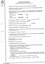
The power maybe estimated from the core area using the following:
Power = Bmax x A^2
Note that this approximate and the area is in sq cm. Bmax depends on core material.
Power = Bmax x A^2
Note that this approximate and the area is in sq cm. Bmax depends on core material.
Last edited:
Thank you! This is what I've read in books from the 1950ies on. Of course, the core material also is unknown to me 😕. Bmax is in Tesla (or Gauss/10.000)?
Best regards!
Best regards!
Yes, B field is in Tesla and Bsat may be taken as 1T for most electrical steels, giving Bmax = 0.6T to 0.7T.
Could you not load the transformer, observe the voltage waveform and use any distortion to predict the loading it can handle?
No, only the cross sectional area of the core is used here. Like I said, this is a simplified formula. The real one involves not only core area but other factors such as window area, current density, number of turns, window fill factor, frequency etc.
P = 4.44 x Acore x Awindow x Bmax x J x Kfill x f
J = 3 to 4 A/mm^2, Kfill = 0.5, f = 50 or 60Hz, etc.
P = 4.44 x Acore x Awindow x Bmax x J x Kfill x f
J = 3 to 4 A/mm^2, Kfill = 0.5, f = 50 or 60Hz, etc.
From open circuit to -10% down in voltage should be a reasonable loading for rated power.Could you not load the transformer, observe the voltage waveform and use any distortion to predict the loading it can handle?
Weigh them, and compare with a transformer catalog. In this case, a vintage catalog; today's products are often more marginal.Which power capabilities can I expect
Oh PLEASE: 5 (FIVE) distracting FULLY unrelated thread suggestions between questions and the answer I am trying to write.
VERY annoying.
If anything, NUKE the "similar threads" feature, it´s useless anyway.

Back to answer:
comparing weight is fine, but assumes similar priorities were taken by designers; the core area method is more accurate so try it.
It still has a possible flaw: it closely hints at total power handling, not much help as to what each winding can supply individually.
Of course, you can use an "educated guess": if a tube amp PT, 80% or more should be used by the HV winding, 20% or less by filaments, etc.
VERY annoying.
If anything, NUKE the "similar threads" feature, it´s useless anyway.
Back to answer:
comparing weight is fine, but assumes similar priorities were taken by designers; the core area method is more accurate so try it.
It still has a possible flaw: it closely hints at total power handling, not much help as to what each winding can supply individually.
Of course, you can use an "educated guess": if a tube amp PT, 80% or more should be used by the HV winding, 20% or less by filaments, etc.
JMF,
besides the last one, any of these trannies come from transistorized Hammonds. The four bigger ones have multiple secondaries, with a 25-0-25 Vac being the most beefy one, feeding the organs' power amplifiers.
Oh, that reminds me that I'll have some closer look at my shelves. There must be another two PSU's with identical transformers, 'cause I've butchered two more Aurora organs...
Best regards!
Accidentally found this table in my files;
remembred this thread; late but here it is anyhow.
Siemens labs used it to order cumstom wound trafos from a winder back in the early 70's;
but works backwards as well;
unfortunately none has the same size as yours .... is most likely based on DIN while yours are U.S.
remembred this thread; late but here it is anyhow.
Siemens labs used it to order cumstom wound trafos from a winder back in the early 70's;
but works backwards as well;
unfortunately none has the same size as yours .... is most likely based on DIN while yours are U.S.
Attachments
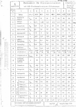
Yes, thank you! I know these DIN cores. The laminations are square shaped, winding window size is one sixth times two thirds the outer length, which is rather large wrt. the lamination dimensions. Power capability depends, as always, on the steel quality.
Best regards!
Best regards!
- Home
- Amplifiers
- Power Supplies
- Guesstimating transformer power ratings