Mistake")
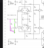
The three FET's should be in parallel and so to the resistors.
Yes. It says 'total resistance is 250' which means the 261 and 6040 are connected in parallel.
Even without that note, the way it is drawn should make that clear.
BTW This is a fine example of how NOT to draw a schematic. Very amateurish. Is this an existing design?
Jan
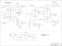
Why would there be 3 fets on the negative voltage rail and 2 on the positive? I posted earlier then deleted my post to check Idss on J112 and J175. J175 should have higher Idss. Also why 0.5 V difference after the fets? Any ideas?
Yes, probably to construct two complementary matched 'devices'. Note that this is all open loop so you must go to heroic measures to get some acceptable linearity from it.
BTW in its original complete form the schematic drawing does make sense so I withdraw my earlier 'amateurish' comment...
Jan
Last edited:
Yes, probably to construct two complementary matched 'devices'. Note that this is all open loop so you must go to heroic measures to get some acceptable linearity from it.
Warning, you are badmouthing the Blowtorch. This is a capital sin.
Warning, you are badmouthing the Blowtorch. This is a capital sin.
Is this the Blowtorch?? Bligh me! I thought it was a well guarded secret? Now anybody and his mom can build one! Not that I would, but in theory.
Would be quite a feat for us pitchfork wielding villagers!
Jan
Last edited:
was it a secret-- !?
atomic bomb on the Internet can be found))))
I do not like secrets! Good Kondo companies! Audionote do not make secrets from their schemes - try again!
I'm probably the first idiot who makes a copy it's all about good old transistors that are no longer available
The last question!?)))
- Is this circuit suitable for a 47K head load MM ?
Last edited:
Is this the Blowtorch??
Close enough
. But closer to the Vendetta SCP-2, though.The CTC Blowtorch is balanced: Uskok preamplifier
Last edited:
- Status
- This old topic is closed. If you want to reopen this topic, contact a moderator using the "Report Post" button.
- Home
- Source & Line
- Analog Line Level
- Guess the photo? blue resistor