Hi, all,
i have a few old Dynacords that need to be restored. These amps deliver 80W of constant power from 2 EL24 running at 750V on a 220V mains (i.e., something around 90W on modern 230V mains). Similar to the GU50, the EL34 demands for an Raa of 8k at these voltages.
One of the amps is nothing more than chassis, headshell, transformers (hopefully ok, tested), and a few poti knobs.
So why not try to set it up with GU50?
There are a few peculiarities, however:
a) mechanically:
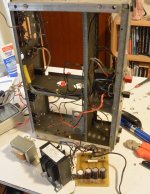
the EL34 are mounted horizontally relatively close to each other, but 2 6L6 can be fitted into that space. Pictures of the situation below.
b) electrically:
the GU50 needs 12.6V. Is a voltage doubler an option? Otherwise i would need to squeeze a heater supply into that space.
the G2 voltage of the GU50 is much lower. In the experiment shown below i changed the stacking of the secondary voltages in order to account for this. Meaningful?
Obvious disadvantage: rail voltage for the anode supply of the preamp is pretty small, possibly a bit too small for the PI stage.
So my question: what Do You think?
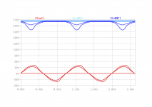
The simulation shows up pretty large distortion - more than 5%. And surprisingly large output power - 135W at 7% THD. Which i cannot believe. Mhmm.
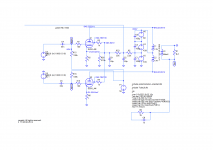
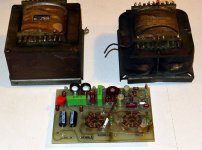
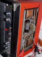
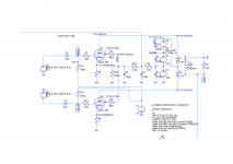
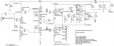
Shown below: the schematics of the original PSU, the numerical experiment, the target transformers and the EL34 board i would like to avoid to reuse, and empty chassis and a fully equipped older version of those amps with two additional chokes in the PSU.
In the simulation i scaled the voltages by a factor of 1.045 = 230V/220V.
As the dead amp was a hybrid amp the PT provides an additional secondary of 45V, i had the idea to add its voltage to the others as well.
The preamp uses around 90mA so it is unclear how much it can actually deliver. Same for the heater supply. In the original amp it feeds two EL34, 1 ECC81 and to lamps each taking 0.3A. Like all other secondary outputs of the transformer.
There is still a replacement transformer set available, on the same core size. This is specified 4.8A for the heater and 260mA on the 45V and the HV rails (plus 100mA for the bias rail). Although that PT has been designed as a drop in replacement, it remains speculative to which detail the original PT is mimicked.
i have a few old Dynacords that need to be restored. These amps deliver 80W of constant power from 2 EL24 running at 750V on a 220V mains (i.e., something around 90W on modern 230V mains). Similar to the GU50, the EL34 demands for an Raa of 8k at these voltages.
One of the amps is nothing more than chassis, headshell, transformers (hopefully ok, tested), and a few poti knobs.
So why not try to set it up with GU50?
There are a few peculiarities, however:
a) mechanically:
the EL34 are mounted horizontally relatively close to each other, but 2 6L6 can be fitted into that space. Pictures of the situation below.
b) electrically:
the GU50 needs 12.6V. Is a voltage doubler an option? Otherwise i would need to squeeze a heater supply into that space.
the G2 voltage of the GU50 is much lower. In the experiment shown below i changed the stacking of the secondary voltages in order to account for this. Meaningful?
Obvious disadvantage: rail voltage for the anode supply of the preamp is pretty small, possibly a bit too small for the PI stage.
So my question: what Do You think?
The simulation shows up pretty large distortion - more than 5%. And surprisingly large output power - 135W at 7% THD. Which i cannot believe. Mhmm.
Shown below: the schematics of the original PSU, the numerical experiment, the target transformers and the EL34 board i would like to avoid to reuse, and empty chassis and a fully equipped older version of those amps with two additional chokes in the PSU.
In the simulation i scaled the voltages by a factor of 1.045 = 230V/220V.
As the dead amp was a hybrid amp the PT provides an additional secondary of 45V, i had the idea to add its voltage to the others as well.
The preamp uses around 90mA so it is unclear how much it can actually deliver. Same for the heater supply. In the original amp it feeds two EL34, 1 ECC81 and to lamps each taking 0.3A. Like all other secondary outputs of the transformer.
There is still a replacement transformer set available, on the same core size. This is specified 4.8A for the heater and 260mA on the 45V and the HV rails (plus 100mA for the bias rail). Although that PT has been designed as a drop in replacement, it remains speculative to which detail the original PT is mimicked.
Attachments
You need a much lower impedance for the G2 supply. According to the LS50 datasheet, G2 current varies from 2x 0,9 mA at idle to 2x 13 mA at full output at these operating conditions. When G2 is fed through a resistor of 22k, the voltage would collapse when driving the amp.
When you look at the schematic of the power supply, you see that the 750V is generated from stacking two individual supplies. In the original EL34 version, G2 is fed from the bottom supply, or around 400V. Use a regulator (not a resistor) to bring it down to 300V for the LS50/GU50. But -more importantly- know what you're doing! These kinds of voltages are much higher than in the typical amp and can be very dangerous.
When you look at the schematic of the power supply, you see that the 750V is generated from stacking two individual supplies. In the original EL34 version, G2 is fed from the bottom supply, or around 400V. Use a regulator (not a resistor) to bring it down to 300V for the LS50/GU50. But -more importantly- know what you're doing! These kinds of voltages are much higher than in the typical amp and can be very dangerous.
Thanks for the response.
First of all - i am fully aware of the danger of these voltages. I have already restored a few of these amps. And the board of the EL34 shows the traces of what they can do - the burns are so deep that it should not be reused...
A word to the regulation: there is actually a regulator, although the most primitive one: R26 does not only act as a bleeder, but also as a shunt regulator.
In order to see the effect i plotted the G2 voltage below, for a very small input signal, a signal short before clipping and a signal at the onset of clipping.
You see the voltage directly at G2 (N007) and the voltage at the junction between G2-resistor and the shunt (N009) which has a very low impedance for NF currents due to the capacitor.
At N009 the voltage is pretty stable. The voltage drop over the G2 resistor is to some degree desired; it protects the grid from overload. Grid load reaches 2.7W - so it might be possible to reduce R3 a bit.
That's going to be used as a bass amp, so it is quite possible that the amp will be driven into saturation, at least occasionally. So i prefer to be conservative and would like to ensure that even massive overload of G2 will not harm it.
Attachments
Addition: i tuned the parameters a bit toward larger G2 voltage, smaller G2 resistance and larger idle current and came out with R23=3.3k instead of O(20k)) and G3/G4=680R.
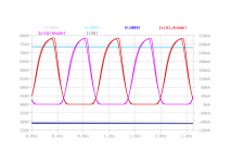
Now i try to get an idea what might be going on in the PSU. In this respect the simulation is pretty tentative: in reality the windings of the transformer are independent. Hence there is no common current path through the real "sources". In the simulation i used some ballpark values for the internal resistance to roughly match the values given in the original schematics.
Anyway, here is a view on what might be expected: You see that the current in the uppermost branch of the stack is about 100mA. And that's something the transformer will most probably be able to deliver (it definitely does 90mA).
I also plotted the anode currents and voltages at the anode and the screen voltage.
The input signal has been chosen slightly smaller than the bias voltage and somewhat larger.
This looks sufficiently reasonable to try it out, doesn't it? Which does not mean that i will not try out using a better regulator some day.
Attachments
Last edited:
For my knowledge these 2xEL34/750V setups were popular for a short period of time as these received a bad reputation of failing by one or another way.
They mostly failed due to improper and careless design of the bias adjustment circuits.
I have three such amps up and running fine - and the first thing to do is to fix the bias pots (low quality, missing failure protection resistors).
2ndly the grid leak resistors are a little bit too large (including the impedance of the bias circuit).
And then the screen stoppers are too small to be able to protect the grids when the power stage is overdriven - a common problem for mostly guitar players.
Of course, the tubes must be carefully biased, not too hot.
And then abuse by some musicians - if You do not match impedances You should not be surprised....
So, if You handle them correctly, they will work reliably. My oldest is from 1966.
But anyway: i want to use the GU50 tubes mainly because of their ruggedness. They are by far not as close to their limits as the EL34 or KT77 would be.
This might make a difference indeed. I always wondered about the EL34 was stated with Va<1250V - how should this work in a push-pull fed by 750V?
Poor quality bias pots have been a common issue - in ss class-AB as well.
Poor quality bias pots have been a common issue - in ss class-AB as well.
The max anode voltage of the EL34 is 800V under full load and 2000V idle. If You build a power stage close to the 800V limit, the voltage will swing up to roughly twice the anode voltage.
Additional remark: i have had very specific and generic points regarding the design of such an output stage, using russian GU50 tubes. I would like to discuss on this. specifically. On topic. And not about EL34 or the like in general.
> discuss on this. specifically. On topic.
You obviously know more about the Imperator than most of us.
You have not identified a problem with using EL34, but with bad bias networks and reckless users. GU50 is a mildly bigger tube but won't survive loss of bias or load.
OTOH, tubes is tubes. Why not go ahead with GU50?
No, you can't readily "voltage double" to the 12V AC level, but 12VDC supplies are easy to find.
I don't see anything like 135W for 800V and 8KCT load. GU50 will not pull-down that low. This and your THD numbers could be re-checked.
The re-checking has already been done in my last contributions. I simply forgot to specify suitable input resistances initially. As long as the anode voltages remain the same, the output that amp with GU50 cannot be significantly larger than that of an EL34 amp.
I've also been tinkering with this idea since more than five years. Besides the issues that you've already mentioned, take care for the insensitiveness (due to low gm) of the GU-50's. A setup that can deliver 80 watts with the stock power and output trannies requires more than double the grid voltage swing at rated power. This is much more than the stock Concertina with half an ECC81 can do. And these GU-50's need to be driven with grid current in a suitable setup. So you'll need a completely another power amplifier board with
- more than twice the stock gain (again, too much for the first ECC81 triode),
- more than twice the stock output swing, and
- amost zero ohms of output impedance, i.e. cathode/source followers.
In addition, you'll need
- regulated (!) 300 Vdc screen supply,
- hence regulated -60 Vdc (at least!) grid bias supply,
- additional 12.6 V 1,6 A (or 25.2 V 0.8 A) heater supply.
I'm in severe doubt that one can additionally throw all of these guts into that rather small case.
In terms of GU-50fying, the bigger siblings of these Eminent II's, Imperator II's etc., the Gigant and Gigant II with their four EL34's are quite another story, though, 'cause their chassis offers much more space for the required supplements. In these big amplifiers the regulated screen supply might even be replaced by rewiring the stock choke for choke PSU input.
Best regards!
Last edited:
Indeed. But with the EL34 this is by no way different, isn't it?A setup that can deliver 80 watts with the stock power and output trannies requires more than double the grid voltage swing at rated power.
This is much more than the stock Concertina with half an ECC81 can do.
Well, according to my sims it can, after a few modifications - at least within the limit of AB1 mode, where the GU seems to behave like a more rugged version of the EL34. Which alone would be worth the effort. But a am actually considering alternatives to the concertina that are able to address at least the onset of grid current of the stages. And maybe supply the G3 with 10-14 V as suggested in the tubes section (and after the success of es345 with this).
And these GU-50's need to be driven with grid current in a suitable setup.
As mentioned: not always, not necessarily, and probably not with this PT.
It is already regulated, but in the most primitive manner. The shunt resistor does quite a good job. I take a really close eye on these aspects in that project.- regulated (!) 300 Vdc screen supply,
- additional 12.6 V 1,6 A (or 25.2 V 0.8 A) heater supply.
I know - the known capacity of the 6V heater is probably a bit limited for a Delon doubler. But that alone is really not a big deal if i plan thoroughly.
I am still looking for reliable info on the G1 leak resistors - info varies wildly from 20k up to 280k or 500k, the latter inWW2 LS50 amps.
I'm in severe doubt that one can additionally throw all of these guts into that rather small case.
1) have a look into an early all tube Eminent 2 (i own one of these, way better that the hybrid version)
2) who forces me to use the headshell, or to use it unmodified? If done right, parts can be positioned above or below the chassis.
the Gigant and Gigant II with their four EL34's are quite another story, though, 'cause their chassis offers much more space for the required supplements.
Where is the choke in the amp below (my G2000 before restauration)?
I will not touch the PS of that amp unless that project has turned out successfully - it is one of my "production" amps. (Again, they probably started production with chokes and changed that pretty soon).
Attachments
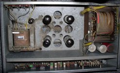
I own four GIGANT and one B2000, all featuring the same PSU/power amplifier section. The choke is beneath the chassis, in all of these.
Best regards!
Btw, I have to stand corrected indeed in comparing EL34 vs. GU-50, as the drive level requirements for the latter isn't twice, but »only« 1.5.
Best regards!
Btw, I have to stand corrected indeed in comparing EL34 vs. GU-50, as the drive level requirements for the latter isn't twice, but »only« 1.5.
Last edited:
Ah yes, i deleted the additional chamber on the PT side from memory... thanks for the reset.
The input demands GU50 roughly correspond to those of a KT88. So i might also check out the PT of a Hiwatt DR201. But this project is a lot on learning the backgrounds how to do things, not only on soldering. So i'm going to try out several alternatives, at leas conceptually. Which feels good because i do already have something working in the back. BTW: with an elevated heater, also an ECC81 can run at voltages in 3rds and give maximum output swing. But keeping short below Ufk_max like in the Eminent, clean 110-120V PP are possible, and that's sufficient for the GU50 in AB1.
3.5% THD ad medium power however is something that ought to be improved.
Maybe it is time to slowly pick this up again (i finally got my problematic Echolette M40 running fine...). Well, and i did some tests on the transformers; they look ok.
But anyway - the ideas in my simulation are far from final. I do plan to use source followers, and after all i've read i do also have the idea to apply a small G3 voltage.
But necessarily a prototype.
It was actually today that i noticed the issue with the holes. My current plan is: start a bass combo project, definitely not before April. Use the Dynacord transformer set, 2 GU50, and an Eminence Beta-12 - powerful in small enclosures, and relatively lightweight. Which means that with some luck i could end up at 20-22kg.
Why regulated? The huge bass amp of ES345 has "just" good, low impedance, screen supply. And i - as i mentioned - was planning some simple shunt regulation.I
- regulated (!) 300 Vdc screen supply,
But anyway - the ideas in my simulation are far from final. I do plan to use source followers, and after all i've read i do also have the idea to apply a small G3 voltage.
Would have been tricky but not a problem.- additional 12.6 V 1,6 A (or 25.2 V 0.8 A) heater supply.
The main difficultiy is the space for the power tubes. Even worse, the holes are to small. And widening the holes, also drilling holes to mount the sockets, is a real pain in this narrow space. Which means no Dynacord headshell.I'm in severe doubt that one can additionally throw all of these guts into that rather small case.
But necessarily a prototype.
Unfortunately, my G-2000 needs a new set of tubes - one of the quartet recently broke. Otherwise G50-fying it would be the natural follow up project.the Gigant and Gigant II with their four EL34's are quite another story,
It was actually today that i noticed the issue with the holes. My current plan is: start a bass combo project, definitely not before April. Use the Dynacord transformer set, 2 GU50, and an Eminence Beta-12 - powerful in small enclosures, and relatively lightweight. Which means that with some luck i could end up at 20-22kg.
I own four GIGANT and one B2000,
And if there weren't the grid leak question it should be pretty easy to drive them from an ECC82/81/ECF802 triode, even from a cathodyne.Btw, I have to stand corrected indeed in comparing EL34 vs. GU-50, as the drive level requirements for the latter isn't twice, but »only« 1.5.
You can see that in my early simulations. I am going to try out several options - with and without cathode follower drivers, with LTP and (preferredly) ampeg like with Pentode+Cathodyne. I think it'll take till January until i can really show a few options.
A recent experiment, still far from usable. Main goal is to check the driver. Although the catodyne should drive that stage with ease as long as gridd current remains small here a variant with an additional cathode follower:

I am looking at the effect of Zeners to stabilize the screen voltage. Remarkably the input voltage for full power will be smaller when G2 is kept smaller, without a significant effect on available power (which seems limited mostly by the PT).
Another issue is to keep the cathode currents below 90-100 mA - that's what the DCN027 is known to deliver safely. And that is apparently the biggest difficulty aside from the queston of the permissable grid leak.
Anothe remark - the power supply: i have the idea of spreading the load on the secondarys of the PT - feed the screens from V2 but the preamp and driver from V4 -capacitively attach a 2nd rectifier to V4. I do not know how to describe that in LTSPICE, so i do temptatively add load resistors R27, R29, R26 and use a seperate voltage source V5.
Unfortunately i cannot show simulation results - the postcript preduced by the windows printer driver under wine does not work at all.
You see that the bis circuit needs a lot of detail - i'm currently more interested in feasibility. But from the Eminents plan the 65V winding will deliver 76V under load with just one way rectification. I will, of course, use a bridge which will probably
Attachments
- Home
- Live Sound
- Instruments and Amps
- GU50 in Dynacord Imperator / Eminent ?