I am thinking of using GU-50 in triode mode and have experimented a bit. G2 is connected to the anode through a 100 ohm resistor. G3 is connected to the cathode.
My experimentation has so far resulted in sparks inside the tubes and/or destruction of the resistor between G2 and the anode.
Here is a schematic with Vak = 335, Vgk = -40 and Ia = 80 mA: http://www.jogis-roehrenbude.de/Verstaerker/LS50.htm If I hook up a tube to my laboratory supply with the same operating point, sparks occur inside the tube. The heater is connected to ground.
Have I received a batch of faulty tubes or is there something that I don't understand?
Looking at the curves for triode mode of the GU50 I think that I(a+g2) will be 120 mA or even more at Vak = 335 V and Vg1 = -40V.

Last edited:
I have once bought such GU50 tubes that required one...two minutes warm up to behave normally.If I hook up a tube to my laboratory supply with the same operating point, sparks occur inside the tube.
Initially they generated g1-current and excessive anode current, if the g1-voltage was supplied thru high resistance (100k).
Try to use cathode resistor instead of fixed bias, connect g1 directly to gnd and let the tubes be in controlled (<100 mA) anode current for couple of minutes.
I had the same problem with date codes 90-xx what may have been the last production runs of GU 50.
They are a tiny bit gassy and start to exhibit gas discharge with voltages over 250v when brand new. Looks like a flash over but does no harm if current limited.
All that is required is to run the heaters only for an hour or so to activate the getter to remove those traces of gas.
After that they are good for 800V.
Only the late date codes seem to be affected, maybe a final production step was left out with the last batches ...
Thanks for your replies! 🙂
The date codes are from 86 and 88.
I have tried the two suggested methods for conditioning the tubes now. Regrettably, without success. The result was a bit different after conditioning - no sparks, instead only a sudden current surge after a few seconds. Despite that I turned off the power as fast as I could, the tube glass broke. The suggestions on current limitation and cathode resistor could probably have avoided that. I have to think if I want to order some new tubes or abandon the idea of using GU-50.
So how did you do the testing ? Can you draw the circuit diagram ?The suggestions on current limitation and cathode resistor could probably have avoided that.

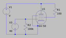
I was trying to test the operating point that I found in the schematic that I linked to in my first post, i.e., Vak = 335, Vgk = -40 and Ia = 80 mA. I connected the tube to my laboratory supply as the attached schematic shows. I adjusted the bias supply to -40 V. Then I turned up the high tension supply. When it got to around 300 V, the current was around 70 mA as expected. After a few seconds, the current meter hit the bottom and the tube glass cracked.
Attachments
That was normal. Had you done the 1...2 minutes burn-in with current/voltage similar or lower than that before the tube broke ?When it got to around 300 V, the current was around 70 mA as expected.
That never happened to me, but my PS had some 150 mA current limit. But that is weird.After a few seconds, the current meter hit the bottom and the tube glass cracked.
I would double check your pinouts.
Short period of normal operation show that pinout should be OK, but could there be bad contact between tube and the socket ?
If g1-connection fails, the plate and screen current would be excessive.
Sometimes old tubes and tube sockets have "corrosion" on their surfaces.
That was normal. Had you done the 1...2 minutes burn-in with current/voltage similar or lower than that before the tube broke ?
I followed your suggestion and tied g1 to ground. I pulled up the voltage until I got 80 mA current. I left it like that for 20 minutes. After that, I connected it in the test set up described above.
but could there be bad contact between tube and the socket?
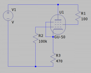
The sockets are Chinese and have no sign of corrosion, but the tube pins were quite corroded. I have a few tubes left so I cleaned one up and conditioned it. For the test, I used a cathode resistor this time to avoid breaking another tube. I connected it like the attached schematic. I increased the voltage until I got 80 mA current and everything appeared stable, but the operating point wasn't anything like expected: Vgk = 38 V, Vak = 100 V.
Attachments
I don't know of any datasheet for the GU50 which clearly states the maximum dissipation in triode mode but the attached datasheet for the LS50 seems to indicate 40 Watt as that maximum (see the last page), and a maximum current of 80 mA (I think; it's hard to read; but atleast less than 100 mA). Also note that the curves for triode mode of the LS50 differ a bit from that of the GU50. At Vak = 300 V and Vg1 = -40 V, the LS50 passes about 65 mA while the GU50 passes about 90 mA.
In the original test set-up with Vak = 335 V and Vg1 = -40 V the current was 120 to 130 mA, giving a dissipation P(a+g2) of 40.2 to 43.6 Watt.
In the original test set-up with Vak = 335 V and Vg1 = -40 V the current was 120 to 130 mA, giving a dissipation P(a+g2) of 40.2 to 43.6 Watt.
Attachments
When I read your post about glass breaking and Chinese sockets, it immediately reminded me of my very first experience with GU50.
Tube glass can melt under extreme overload after minutes of read plating under run-away conditions, but shattering immediately is very unusual and points to mechanical stress rather than electrical overload.
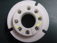
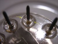
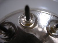
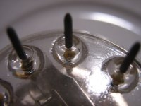
If you have those Chinese sockets asshown in my attachments, they have a reputation of damaging the tubes, and I can confirm that by my own experience.
The point is that the socket springs have too much space to move, so it is easily possible to insert the tube such that a pin misses the center of a spring and is caught beween spring and sidewall of the hole in the ceramic; when pushing the tube down into the socket this pin experiences a mechnical stress sideways which almost inevitably causes a crack in the all-glass base of the GU50.
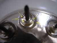
Have a look at my pictures ... the initial crack can be hard to spot, use a magnifying glass.
In my case my first GU50 worked until the day after when enough gas had leaked into the envelope to turn it into a big glow tube.
So what about a failure mechanism where a small crack at the tube base happens when inserting the tube pins out of center, causing air leakage.
Lots of gas in a tube turns it into a big gas discharge device, lots of current to heat up the gas anddevelopment of enough internal pressure to break the envelope ... ?
So make shure that all 8 pins hit the center of their respective contact spring before pushing the tube down.
I do that by rotating the tube base and rolling pins into their seats one by one, inspecting every pin with a magnifying glass before I push down with force.
Tube glass can melt under extreme overload after minutes of read plating under run-away conditions, but shattering immediately is very unusual and points to mechanical stress rather than electrical overload.
If you have those Chinese sockets asshown in my attachments, they have a reputation of damaging the tubes, and I can confirm that by my own experience.
The point is that the socket springs have too much space to move, so it is easily possible to insert the tube such that a pin misses the center of a spring and is caught beween spring and sidewall of the hole in the ceramic; when pushing the tube down into the socket this pin experiences a mechnical stress sideways which almost inevitably causes a crack in the all-glass base of the GU50.
Have a look at my pictures ... the initial crack can be hard to spot, use a magnifying glass.
In my case my first GU50 worked until the day after when enough gas had leaked into the envelope to turn it into a big glow tube.
So what about a failure mechanism where a small crack at the tube base happens when inserting the tube pins out of center, causing air leakage.
Lots of gas in a tube turns it into a big gas discharge device, lots of current to heat up the gas anddevelopment of enough internal pressure to break the envelope ... ?
So make shure that all 8 pins hit the center of their respective contact spring before pushing the tube down.
I do that by rotating the tube base and rolling pins into their seats one by one, inspecting every pin with a magnifying glass before I push down with force.
Attachments
Yes.
G3 is necessary in pentode mode to compensate plate current kink. In triode mode, (G2 connected to plate) there is no such problem to solved with G3. Therefore there is no need to have "operative" G3, i. e. connected to cathode. But when both G3 and G2 are connected to plate, the tube has better characteristics (higher gm and lower rp)
G3 is necessary in pentode mode to compensate plate current kink. In triode mode, (G2 connected to plate) there is no such problem to solved with G3. Therefore there is no need to have "operative" G3, i. e. connected to cathode. But when both G3 and G2 are connected to plate, the tube has better characteristics (higher gm and lower rp)
etched right below the ГУ-50 mark, month in roman numbers left of the tube maker logo, year to the rightSame here, corroded pins. Where can I find the date code?
I bought 4.
so in this example VI (Ulyanov) 84 = June 1984 from Ulyanov factory
Attachments

- Home
- Amplifiers
- Tubes / Valves
- GU-50 Triode Mode