What about the bridging board, how is that going?
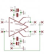
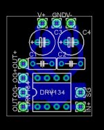
I've drawn one quickly, but I'm not sure about the decoupling. The datasheet doesn't mention it, and on the drawings, they only have 1uF(doesn't mention if it's electrolytic, film or tantalum). On this PCB I have put 100nF ceramics and 120uF elecrolytics. No PSU on the PCB.
Wouldn't it be a good idea to implement the PSU for this one on the rectifying bridge boards?
But how are we going to get the +/-18V? By using adjustable regulators like LM3x7, linear regulators like LM7x18, zener, series resistors or anything else?
Attachments
Alcaid said:
Wouldn't it be a good idea to implement the PSU for this one on the rectifying bridge boards?
But how are we going to get the +/-18V? By using adjustable regulators like LM3x7, linear regulators like LM7x18, zener, series resistors or anything else?
I would be tempted to get the supply voltage from filter capacitors on amp's board (1000u). All you need then is regulators on a bridging board, providing +/-15V and some small bypass caps after regulators (10-100u would be fine). I would use the low dropout type reg, I mentioned somwhere else on the forum.
The connection points on bridging board should match connection points on amops boards (to create compact module).
His excellent piece of work can be downloaded herePeter Daniel said:Here's another pic. Now, that's the board one can be proud of😉
Well done, Upupa Epops.
It's only schematics and pcb layout, partslist will come.
Although I rather like simplisitc approaches the board looks really well designed.Here's another pic. Now, that's the board one can be proud of
Only thing that I don´t like is the position of the heatsink, the weight and the actual size causing a lot of stress on the PCB.
(Even on the pictures you can see it´s bend)
Working in the repair business and knowing that these chips are almost indestructable I´d almost bet my butX on what´s defect first...
You´d at least have to screw the PCB where the heatsink sits with more screws and the heatsink itself to the chassis although I´d rather plan it different or use flanged heatsinks and mount the PCB to the heatsink, not the other way round.
Objection is rejected
To joensd : If you look below this heatsink, you will see there 6 holes 😎 . This profile is standard 100*100*40 mm. If you turn it 90 degrees, you can use all holes. Also as heatsink you can use an " U " profile, square pipe or " jackel " pipe. All this heatsinks you can on oposite side screw on to cassis or another bigger heatsink. Belive me, I was thinking about honestly 😎 and this amp is quite universal.
To joensd : If you look below this heatsink, you will see there 6 holes 😎 . This profile is standard 100*100*40 mm. If you turn it 90 degrees, you can use all holes. Also as heatsink you can use an " U " profile, square pipe or " jackel " pipe. All this heatsinks you can on oposite side screw on to cassis or another bigger heatsink. Belive me, I was thinking about honestly 😎 and this amp is quite universal.
The biggest stress at his board is caused by the eminent Wago connectors when you connect. These new Wago's with levers reduces the bending forces a lot. If you use Wago 236 without levers and use a screwdriver you will create huge stress and even huger stress if you have SMD parts. No, this rather small board can take this heatsink if the pcb is not mobile, at home like.joensd said:Only thing that I don´t like is the position of the heatsink, the weight and the actual size causing a lot of stress on the PCB.
(Even on the pictures you can see it´s bend)
I didn´t have a look at P-A´s pdf-file that´s why I obviously haven´t seen the 2 screws going through the heatsink.To joensd : If you look below this heatsink, you will see there 6 holes
That´s what I meant with attaching the heatsink to the chassis.
2 screws through the chassis, PCB and heatsink which should be enough to take any stress from the PCB.
Congratulation on a job well done.
What do you think about your project and the chips used?
Any comparisons with discrete amps?
Regards
Jens
To joensd : If you can and some of others guys too, I can write about this project more, but I mean, that should be better do it on new thread, 'cos this is Brian's battlefield 😉 , isn't truth ?
Check hereUpupa Epops said:To joensd : If you can and some of others guys too, I can write about this project more, but I mean, that should be better do it on new thread, 'cos this is Brian's battlefield 😉 , isn't truth ?
http://www.diyaudio.com/forums/showthread.php?s=&postid=411485#post411485
Hi, I just wanted to know if BrianGT had had a chance to evaluate the prototypes of the board yet. Is there an ETA for the final boards?
Thanks,
Sébastien
Thanks,
Sébastien
last time i asked a few day's ago he was ordering em the prototypes that is brian and peter are still working on it😉
Brian,
any update on this project? Is there any plan to incorporate Nelson Pass's super symmetry GC into the schematic?
any update on this project? Is there any plan to incorporate Nelson Pass's super symmetry GC into the schematic?
agent.5 said:Brian,
any update on this project? Is there any plan to incorporate Nelson Pass's super symmetry GC into the schematic?
There are no plans to incorporate NP's SuSy stuff into the GC, as it is patented technology. I wouldn't want to infringe upon his patent. It is also an unproven design, that so far, only looks good on paper.
Here is a screenshot of the current layout, which I still have delayed making the prototypes, as I have been busy with the LM3875 kits. I will work hard to get the prototype boards ready to order tomorrow.
An externally hosted image should be here but it was not working when we last tested it.
--
Brian
BrianGT said:
There are no plans to incorporate NP's SuSy stuff into the GC, as it is patented technology. I wouldn't want to infringe upon his patent. It is also an unproven design, that so far, only looks good on paper.
Here is a screenshot of the current layout, which I still have delayed making the prototypes, as I have been busy with the LM3875 kits. I will work hard to get the prototype boards ready to order tomorrow.
An externally hosted image should be here but it was not working when we last tested it.
--
Brian
Brian,
Any progress on these?


- Status
- Not open for further replies.
- Home
- Group Buys
- Group order of non-inverted LM4780 pc boards? Anyone interested?