I solder then cut. Then I desolder and move the component to the CORRECT location. That way it already has the short leads. No stress on the part that way, just the builder.
Jean-Paul,
Cut first, don't bend .... How do you keep the component from falling off during soldering? I'm anxiously waiting for a clever answer.
I never said not to bend the wire. Please bend the lead wire a bit over the pad, then cut the excess wire off and solder it. No way the component can fall out that way. The wire touches the copper-pad directly and solder keeps it in place. Another positive side-effect is that the centre of the leadwire will be slightly covered with solder and corrosion is prevented. Some japanese manufacturers use this technique for quite some years as a standard.
Cutting after soldering is responsible for 40 % higher failure rate in a lifespan of some years IIRC. I repaired Philips gear that was soldered before cutting. Older Philips machines have those small cracks in the soldering because of the cutting and a wrong way of wave soldering. Much failures because of that. The cutting with standard cutters pulls the leadwire a bit out of the joint thus putting mechanical stress on the soldering ( which itself is relatively weak ). A crack might occur hich looks like a small circle if you look at it with a magnifying glass.
Sorry if this all seems offtopic and exxagerated ( which it isn't ) but it will pay off in the long term. With high current joints it can pay off in the short term 😉
jean-paul said:
Please bend the lead wire a bit over the pad, then cut the excess wire off and solder it.
What about soldering, cutting, then reheating the pad to get a more solid connection?
--
Brian
That's double work but ends up the same with the difference that the component is heated twice which may not be beneficial for its lifetime.
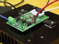
press resistors against the board's surface
Just thought I'd mention for the newbies that if the resistor is handling a few watts or more, it's better to keep it a bit above the board, so air can circulate.
Variac said:
Just thought I'd mention for the newbies that if the resistor is handling a few watts or more, it's better to keep it a bit above the board, so air can circulate.
That is what I did for my mini-aleph boards. I like the way that it looks also.
--
Brian
Attachments
jean-paul said:offtopic again, but those thermal pads are pretty thick. What material are they made of ?
Aluminum Oxide by Aavid. I bought them from Mouser. I will include a pair for you with your pcbs. (just started packaging the stuff this morning and addressing it to go out)
--
Brian
Please include 4 pieces if possible and add the costs to the total. I am curious how they function compared to the thinner mica and silicone rubber pads.
BTW how does Mini Aleph compare to the LM3875 amp ?
BTW how does Mini Aleph compare to the LM3875 amp ?
I like them a lot. They are easy to use and there is not at all any danger of getting short. They also reduce capacitive coupling.
Some of us are brave enough to still use berylium oxide pads, as they might offer even better performance😉
Some of us are brave enough to still use berylium oxide pads, as they might offer even better performance😉
Performance is of less importance than health risks if you ask me.
Some time ago I was in a recycling factory where they dismantled large volumes of electronics gear and separated the metals by heavy grinding everything and filtering ( magnetic and vibration ) afterwards. I was at the copper department and I asked the guy who operated the machinery for possible health risks with small amounts ( assumed ) beryllium copper being grinded as a heavy copper smell was around and copper dust was in the air. The guy was wearing a light air filter which he took off and he replied beryllium was of very small risk as it's forbidden for several years now in Europe. Now just think that only a few milligrams of Beryllium ( oxide ) in human lungs can be causing severe health problems.
You should consider that all potentially dangerous materials end up somewhere in the recycling chain sometime. I doubt if the people that work in India in recycling factories wear filters at all. I recently saw a program how children over there remove the asbestos we liked to use in ships without any protection.
A better environment is in the details as well. If it's not dangerous to you now it can be dangerous for others later....
Some doubt this way of thinking will pay off but as an example I can think of the USA which alone is responsible for one third ( 1/3, 33 % ) of the worlds air pollution. Suppose people and industry would be more conscious over there and you get the picture. It's all in the numbers.
Is 2X25V OK???
Hi There,
As I await the next round of the PCB offer, I am building a point-to-point Power supply and it is going major problematica...Please confirm if my using a 300VA, 2X25V is a problem? does it have to be 22V? FYI I am using the MUR860 + 4.7uF, 50V, BG (normal type).
Thanks
Karma
Hi There,
As I await the next round of the PCB offer, I am building a point-to-point Power supply and it is going major problematica...Please confirm if my using a 300VA, 2X25V is a problem? does it have to be 22V? FYI I am using the MUR860 + 4.7uF, 50V, BG (normal type).
Thanks
Karma
2x25V should be just fine. Up to 2x30V would stay within National's voltage rating, and I wouldn't be too afraid to push it slightly higher. They are cheap chips, after all.
tpenguin said:2x25V should be just fine. Up to 2x30V would stay within National's voltage rating, and I wouldn't be too afraid to push it slightly higher. They are cheap chips, after all.
Cheers!.. I wondered where my powersupply connection went kaput!??? I set it up as BrianGT's/Peter's schematics.....the caps sure smells like nothing!!@##.......

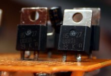
BTW the MUR 860, the anode is the right leg??? i.e. when one looks at it from the insulated side???
Thanks.
Thanks, a doubt crept up as the K & A is rather strangely fonted and the A (Anode) is above the right probe whilst the K(Assumed Ka!!....cathode) is in the middle of the two probe. I am sure my extreme audio knowledge is rather blatantly exibited, thank you all who are helping.....Peter Daniel said:It is clearly marked on a case wit K and A.
Thuji che,
Karma
Peter Daniel said:A is on the anode side and K is on the cathode side, it can't be mistaken.
Here is my Mur860 with the markings.
Attachments
tops said:
BTW the MUR 860, the anode is the right leg??? i.e. when one looks at it from the insulated side???
It is correct
- Status
- Not open for further replies.
- Home
- Group Buys
- Group order of non-inverted LM3875 pc boards? Anyone interested?