is there a chance that you will at least semi-permanently sell these pcb's / gainclone kits? Ive got enough now for one premium kit and so does my brother, but ive got to take my girl to prom  so i cant get all that i would like now (5 channel ht amp and 200 watt bridged sub amp). Will there be a third order? just curious.
so i cant get all that i would like now (5 channel ht amp and 200 watt bridged sub amp). Will there be a third order? just curious.Chris8sirhC said:is there a chance that you will at least semi-permanently sell these pcb's / gainclone kits? Ive got enough now for one premium kit and so does my brother, but ive got to take my girl to prom
I can easily offer pcbs for a long time. The kits will be offered as long as there is demand for them.
I will also have more projects to offer as kits in the future.
--
Brian
Please let us know when premium kits are available
Brian,
Please let us know when premium kits are available again. I want one! ...or two. Great stuff!
I think a lot of us would be interested in a premium monobloc kit as well.
Best,
KT
Brian,
Please let us know when premium kits are available again. I want one! ...or two. Great stuff!
I think a lot of us would be interested in a premium monobloc kit as well.
Best,
KT
Brian, I just read the manual you wrote on your website ( after I built the amp 😉 ) and I want to point to the soldering procedure you describe.
Never cut the excess wire after soldering but do it before soldering. Many failures do occur when mechanical stress is applied to the joint ( only after some time ). The way I describe it is standard procedure in defense electronics. Cut first, then solder for long term reliability. Bending the wire a bit over the pad is better for the joint but it is more dificult to remove the component in question when repair or mods have to be done.
I also missed the component numbers ( R1, R2 etc. ) in the schematic but they were shown in the parts list so that is not very important.
Just some tips to make the manual even better than it is now.
Hello Brian,
I have not received my kits yet. I live in Saskatoon Saskatchewan Canada. How much longer should it be?
Thanks
KevinLee
I have not received my kits yet. I live in Saskatoon Saskatchewan Canada. How much longer should it be?
Thanks
KevinLee
KevinLee said:I have not received my kits yet. I live in Saskatoon Saskatchewan Canada. How much longer should it be?
Typical transit time USPS>Canada Post is 2-14 days (althou i have seen it take longer)
dave
KevinLee said:Hello Brian,
I have not received my kits yet. I live in Saskatoon Saskatchewan Canada. How much longer should it be?
Thanks
KevinLee
Kevin,
I just sent you an e-mail about your order. I am sorry for the delay, and you should receive it soon.
--
Brian
jean-paul said:Brian, I just read the manual you wrote on your website ( after I built the amp 😉 ) and I want to point to the soldering procedure you describe.
Never cut the excess wire after soldering but do it before soldering. Many failures do occur when mechanical stress is applied to the joint ( only after some time ). The way I describe it is standard procedure in defense electronics. Cut first, then solder for long term reliability. Bending the wire a bit over the pad is better for the joint but it is more dificult to remove the component in question when repair or mods have to be done.
I also missed the component numbers ( R1, R2 etc. ) in the schematic but they were shown in the parts list so that is not very important.
Just some tips to make the manual even better than it is now.
Interesting prospective on soldering. I have always cut off the wire after soldering. I have never heard of anyone cutting the wire off before soldering, since the longer leads bent to the side help keep the component in place while soldering. I understand the reasoning behind this, but I am unsure how much of a problem this would actually cause. I will put your suggestion in the manual, below my instructions, so that others can consider this advice.
How about the idea of reheating the soldering joint after the leads are clipped off, to avoid this problem?
Also, as for bending the leads to the side, this does make them harder to remove for repairs, but I would imagine that it would provide for a much better connection, in addition to keeping the components in place while soldering.
I will add new schematics to the manual in the near future.
--
Brian
Jean-Paul,
Cut first, don't bend .... How do you keep the component from falling off during soldering? I'm anxiously waiting for a clever answer.
Cut first, don't bend .... How do you keep the component from falling off during soldering? I'm anxiously waiting for a clever answer.
If anyone who placed an order before April 8th, hasn't received their order, drop me an e-mail and I will look into it for you.
--
Brian
--
Brian
fcel said:Jean-Paul,
Cut first, don't bend .... How do you keep the component from falling off during soldering? I'm anxiously waiting for a clever answer.
I normally use a spring tweezer the one that is closed unless pressed by index finger and thumb to open the tip clamps. The spring tweezer's spring action is very soft and will not clamp too tight. If you start with the lowest profile parts on the PCB you should be ok. Occasionally some parts will get in the way then I use blue tac instead.
These methods may not needed for the seasoned diyers, but it seems good for newbies like myself.
Regards,
Chris
So, you've got one hand holding the tweezer, one hand holding the soldering iron, how do you feed the solder? Sorry, I don't mean to be making fun of this but I really would like to know what is the correct way.
I use one of those clamp stations to hold the pcb and find a horizontal level for the PCB that the tweezer will stay put with the part. The tweezer even though has soft spring but yet strong enough to hold itself in place with the part and the pcb between its clamps. So I can use two hands to do the soldering, some people use the mouth feeding method I heard.
Chris
Chris
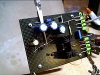
I should have taken a bigger picture, so that it can not be accused of cheating by using one hand to hold the tweezer and one hand to take the picture. never mind anyway give it a try... it help me a lot...I hope it will help others...
😎
😎
chris ma said:the mouth feeding method I heard
I'm familiar with that technique... sometimes i just pretend i have 3 hands too.
Some hemeostats & a little vise sure come in handy
dave
This is too slow and not convenient. When I assemble PCBs, I install all resistors (20 pcs or so at once), flip the board and put it on 1/2" foam (upside down), clamp 2 sides to the table (or put weights on both ends) to squeeze the foam. The foam produces enough pressure to press resistors against the board's surface. Then I solder all the leads and then I cut them. I wouldn't even think twice about cutting them before soldering.
I'm using $30 side cutters, so they are very delicate and don't produce any tension😉
I'm using $30 side cutters, so they are very delicate and don't produce any tension😉
You do know that this OT subject came up because Jean-Paul said "cut first & don't bend ..... ".
Yes, I know. I also know that J-P has very high quality standards and at one time he used to drop equipment on the floor, to make sure it will sustain any future abuse.😉
- Status
- Not open for further replies.
- Home
- Group Buys
- Group order of non-inverted LM3875 pc boards? Anyone interested?