Came back from the office and my iron was hot and ready to go 😉 Then I started soldering...
Every parts are in place now. This is becoming to look good 😀 Before I can listen to this baby I have a few questions. For those that might be tempted to ask, yes I did search but I just can't seem to find what I am looking for. And with more than 100 pages, I just don't feel like reading this thread all over again.
The rectifier is connecter to the amp board. I've got the remaining holes to fill on the amp board: (from left to right) OUT, OG, SG, IN and CH. I understand that OUT is the output of the amp, SG probably means Star Ground, and IN is the input.
1- What are OG and CH for ?
2- I will connect the input ground, output groud and the star ground together. Is there anything else I need to connect to it ?
3- Since I am building two monoblock amps that will reside in the same case, will I need to connect the 2 star grounds (one from each amp) together ?
4- Last but not least, how do I go about to measure the DC offset ? Source pluged in or not ? Speakers pluged in or not ? Volume control all the way up or down ?
Hi,fireman said:Came back from the office and my iron was hot and ready to go 😉 Then I started soldering...
Every parts are in place now. This is becoming to look good 😀 Before I can listen to this baby I have a few questions. For those that might be tempted to ask, yes I did search but I just can't seem to find what I am looking for. And with more than 100 pages, I just don't feel like reading this thread all over again.
The rectifier is connecter to the amp board. I've got the remaining holes to fill on the amp board: (from left to right) OUT, OG, SG, IN and CH. I understand that OUT is the output of the amp, SG probably means Star Ground, and IN is the input.
1- What are OG and CH for ?
2- I will connect the input ground, output groud and the star ground together. Is there anything else I need to connect to it ?
3- Since I am building two monoblock amps that will reside in the same case, will I need to connect the 2 star grounds (one from each amp) together ?
4- Last but not least, how do I go about to measure the DC offset ? Source pluged in or not ? Speakers pluged in or not ? Volume control all the way up or down ?
OUT = Output of the amp
SG = Signal ground
IN = Input signal
OG = Output ground
CH = Chassis ground (aka Star ground)
Like you mentioned, you can just skip the SG and OG and connect those two (along with the CH?) to your star ground point.
I think, from reading other posts on this forum, that you DO need to connect the star grounds from both amps together.
--Ferdi
fireman said:1- What are OG and CH for ?
2- I will connect the input ground, output groud and the star ground together. Is there anything else I need to connect to it ?
3- Since I am building two monoblock amps that will reside in the same case, will I need to connect the 2 star grounds (one from each amp) together ?
4- Last but not least, how do I go about to measure the DC offset ? Source pluged in or not ? Speakers pluged in or not ? Volume control all the way up or down ?
You connect input signal ground wire to SG, output ground wire (to binding post) to OG, none of those need to be connected with a star ground.
CH means chassis ground, and you might connect wires from those points (on two channels) to a common point on a chassis. I found it quite convenient to not isolate negative binding posts (from OG) and those connect directly to chasiss. I'm not running any wires from CH then.
my kit just arrived in the post in the UK.
cant wait to build it! shame im working today, and then the weekend as well! 🙁
thanks for the excellent group buy, communication and delivery Brian and Peter!
Amit
cant wait to build it! shame im working today, and then the weekend as well! 🙁
thanks for the excellent group buy, communication and delivery Brian and Peter!
Amit
Thanks Peter and ftjandra for the information regarding my first 3 questions. Now, what about the 4th one ?
Finallly, has the schematic of the revision B boards been published ? If so, where can I find it ?
Just like damitamit and a whole bunch of people, I am working today so I'll have to wait until tonight to start working on my amps. Fortunately, there is not much work to be done before I can hear these babies.
Once again, thank you Brian and Peter for your excellent work with this group buy.
fireman said:4- Last but not least, how do I go about to measure the DC offset ? Source pluged in or not ? Speakers pluged in or not ? Volume control all the way up or down ?
Finallly, has the schematic of the revision B boards been published ? If so, where can I find it ?
Just like damitamit and a whole bunch of people, I am working today so I'll have to wait until tonight to start working on my amps. Fortunately, there is not much work to be done before I can hear these babies.
Once again, thank you Brian and Peter for your excellent work with this group buy.
You can find online manual here: http://www.briangt.com/nigc_kit-users_guide.pdf
DC offset is measured on binding posts (between + and - outputs). Check both with pot up and down as it's setting affects offset. Connecting speakers does not affect this value, but initially for safety purposes, measure offset without speakers connected.
DC offset is measured on binding posts (between + and - outputs). Check both with pot up and down as it's setting affects offset. Connecting speakers does not affect this value, but initially for safety purposes, measure offset without speakers connected.
Status Update for orders
As for the current status of international orders. I have mailed 2 packages up to Peter this week, one on Tuesday and one on Thursday. The Fedex tracking information says that they will arrive on 13th, and the 16th. I am hoping that the ongoing Canadian custom strikes don't effect the shipping time for this. I shipped via Fedex Ground this time, with the correct postal code. Fedex offers much better tracking information that USPS. I mailed the parts as two seperate smaller boxes, to try to make the customs go faster.
As for the US orders, I am waiting for the next Digikey parts to get here on next Tuesday, the 10th, and then I will start shipping all the remaining orders.
This latest phase of orders (with the Rev2 boards) has been quite successful, with orders for almost 250 kits. Currently 80% of the US orders, and 70% of the international orders have been shipped out. I will work with Peter to get all remaining orders shiped out ASAP.
I am still backlogged in e-mails, and am slowly catching up. I am sorry if your e-mail hasn't been answered yet. I will try to get all e-mails answered in the near future. I recently moved to a new house, and have been very busy, combined with not having e-mail at home for a week.
--
Brian
Re: Status Update for orders
Our customs is having a strike?
dave
BrianGT said:the ongoing Canadian custom strikes
Our customs is having a strike?
dave
Re: Re: Status Update for orders
That's what I was told recently.
planet10 said:
Our customs is having a strike?
dave
That's what I was told recently.
another amp has arrived!!
Today, my premium kit arrived, all the way to little ol' New Zealand....... this allows me to finally finish up my 6 channel amp. The iron is warming up right now, so expect some photos shortly....
SteveM
PS Brian & Peter.... great work.....again!
Today, my premium kit arrived, all the way to little ol' New Zealand....... this allows me to finally finish up my 6 channel amp. The iron is warming up right now, so expect some photos shortly....
SteveM
PS Brian & Peter.... great work.....again!
Connect IN to SG (= shorting the input) and measure the DC voltage between OUT and OG with a multimeter.fireman said:Thanks Peter and ftjandra for the information regarding my first 3 questions. Now, what about the 4th one ?
/U.
Another problem...
I did that and got 10.2 mV on one channel and 5.4 mV on the other !
😀
Now if only I could understand why my pot is not working properly... As I explained in this thread, I have to turn the pot almost half way up before I can hear something. One click before and I don't hear a thing. Then the next click and it starts blasting !!! It's not over the edge loud but it's plenty loud that I wouldn't listen to the music at that level...
Anybody has any idea what might be causing this problem ?
Nisbeth said:
Connect IN to SG (= shorting the input) and measure the DC voltage between OUT and OG with a multimeter.
/U.
I did that and got 10.2 mV on one channel and 5.4 mV on the other !
😀
Now if only I could understand why my pot is not working properly... As I explained in this thread, I have to turn the pot almost half way up before I can hear something. One click before and I don't hear a thing. Then the next click and it starts blasting !!!
It's not over the edge loud but it's plenty loud that I wouldn't listen to the music at that level...Anybody has any idea what might be causing this problem ?
It always amazes me what can find with a little googling ! 😉 I found this thread and also this one which are related to my "Alps" pot. While I could not identify if there was something wrong with it, I did find out it is most probably a fake Alps pot. 
Also, while doing more tests, I found out it is a linear pot. That doesn't tell me why the sound sudently "jumps", but at least I know it will not behave like a log pot. I went looking in my junk box and finally found an old Alps (this one is the real thing) mono pot. It's a 10K log pot and when I tried it with one channel it worked wonderfully ! 😀
So I'm back looking for a pot or maybe an attenuator to finish my GC.
its a common problem... I guess. The resistive path is broken at that point, so at ground side you have a resistor to ground and beyond that point, you have a resistor to max. signal side. Depending on the value, and the input impedance of next stage, you can not have all the signal passing so the volume is not the maximum one.
My guess...
My guess...
there's another possibility... oh, sorry i'm posting off topic messages.. but this is last one.
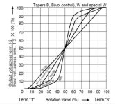
Have you seen this alps graph??
http://www3.alps.co.jp/pdf/2004pdf/pdf_e/Potentiometer/Resistance.pdf
maybe the W and W special types are like the model you have.
One more note: I have four or five ALPS motor driven pots... all have the ALPS logo engraved at left side. I think immitation does not have it.
Hope to help.
Hisatugo
Attachments

Peter and Brian some people have thoughts like these above. It's about order, payment and delivery status. I have an smart idea. See private message 🙂
Sing baby sing !!!
I finally figured out the problem with my "Alps" pot. Once again the problem was behind the soldering iron
I had only briefly taken a look at the legs numbers on the back of the pot. I my head, they read 1-2-3-4 but this picture shows 4-3-2-1 When I resoldered everything to the correct legs, everything fell into place.
I just couldn't wait any longer and mounted everything on a piece of plywood, went upstair, fired up my el cheapo DVD player, tossed Eric Clapton's Live at Hyde Park DVD and started to listen to my babies !!! Here are a few pictures:
Picture 1
Picture 2
Picture 3
The mid and treble are a little forward right now. The bass is good though. I guess they'll eventually blend in a little better as the amps burn in. Now I guess I'll have to start thinking about the case... Gotta go listen to my babies
I finally figured out the problem with my "Alps" pot. Once again the problem was behind the soldering iron
I had only briefly taken a look at the legs numbers on the back of the pot. I my head, they read 1-2-3-4 but this picture shows 4-3-2-1
When I resoldered everything to the correct legs, everything fell into place.I just couldn't wait any longer and mounted everything on a piece of plywood, went upstair, fired up my el cheapo DVD player, tossed Eric Clapton's Live at Hyde Park DVD and started to listen to my babies !!! Here are a few pictures:
Picture 1
Picture 2
Picture 3
The mid and treble are a little forward right now. The bass is good though. I guess they'll eventually blend in a little better as the amps burn in. Now I guess I'll have to start thinking about the case... Gotta go listen to my babies
nice i like the leds. i was going to post something last nite about the 4 pin pot but i was shure you would figure it out😀
do the heatsinks get warm?
do the heatsinks get warm?
karma said:nice i like the leds. i was going to post something last nite about the 4 pin pot but i was shure you would figure it out😀
I like the leds too. 🙂 I thought about wiring them to one of the PS rails but decided against it as these are often described as noisy little beasts. I had read somewhere in this thread that winding a wire few turns around the toroid works great also. I also felt that it might be less noisy that way since it is not directly connected to the PS.
do the heatsinks get warm?
Barely ! I must say that I was a little surprised as many people have commented that the chip became quite warm during the first hours of operation. I am definitely not a fan of loud music so that might explain why it remained cool. These are not the definitive heatsinks BTW. Depending on the layout of the case, I might attach them directly to the sides or back of the case.
- Status
- Not open for further replies.
- Home
- Group Buys
- Group order of non-inverted LM3875 pc boards? Anyone interested?