I ordered the boards this afternoon, and will have they will be done in a week, and then shipped to me, so I will have them by a week from this Friday. I ordered a large chunk of parts (maxed my credit card out), and once the paypal funds transfer to my bank account, I will be able to order the rest (Paypal takes 4-5 days to do so). I should hopefully get all the parts by mid next week, then the kitting process begins.
I am still taking orders, as I will keep on ordering parts for a while longer.
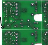
Here is a picture of the pcb. I worked with Peter Daniel, to get the design cleaned up, and added mounting holes that will work perfectly with his chassis that he is getting manufactured to go along with this order:
http://www.diyaudio.com/forums/showthread.php?postid=339460#post339460
I am working on an instruction manual, along with a FAQ (frequently asked questions) for the gainclone.
I am still taking orders for a while longer:
http://brian.darg.net/order
EDIT: Just wanted to mention that I paid extra and got the boards with a red soldermask, so they will look pretty good.
--
Brian
I am still taking orders, as I will keep on ordering parts for a while longer.
Here is a picture of the pcb. I worked with Peter Daniel, to get the design cleaned up, and added mounting holes that will work perfectly with his chassis that he is getting manufactured to go along with this order:
http://www.diyaudio.com/forums/showthread.php?postid=339460#post339460
I am working on an instruction manual, along with a FAQ (frequently asked questions) for the gainclone.
I am still taking orders for a while longer:
http://brian.darg.net/order
EDIT: Just wanted to mention that I paid extra and got the boards with a red soldermask, so they will look pretty good.
--
Brian
Attachments
That is an entirely different board ! Glad you included mounting holes for better building. Thanks for all the energy you're putting in this project.
jean-paul said:That is an entirely different board ! Glad you included mounting holes for better building. Thanks for all the energy you're putting in this project.
Thank Peter as well, as he has helped me with the countless iterations that this board has gone through in the last week.
--
Brian
Very nice boards, Brian (and Peter). They should look great with the red solder mask. I'm still working on trying to get polygon planes to come out the way I want them in Protel.
Wow, that looks great. Hookup diagrams would help too. It looks like a dual secondary transformer should be hooked up 'straight', i.e. hot to hot and neutral to neutral on both secondaries. In other words, if you had a transformer with a single center tapped secondary, the center tap would go to AC1H and AC2N? It would be nice to know this, so I don't blow things up the moment I apply power 🙂 Diode orientation, that's another area where beginners could easily make a mistake (heck, I can see myself getting confused, and I'm not *that* much of a beginner) Or, if you're supplying a printed schematic with the kit, then mark the points on the schematic with their PCB names.
Also, on the audio boards, it looks like PG+ is the ground for V+. But on the PS board, it looks like PG- is the ground for V+. Is that a typo, or am I just missing something here? Wouldn't the grounds of the channels cross over if they're connected 'straight' from the PS board to the audio board?
I hope those aren't really stupid questions 🙂
Saurav
Saurav said:... Diode orientation, that's another area where beginners could easily make a mistake (heck, I can see myself getting confused, and I'm not *that* much of a beginner) Or, if you're supplying a printed schematic with the kit, then mark the points on the schematic with their PCB names.
Also, on the audio boards, it looks like PG+ is the ground for V+. But on the PS board, it looks like PG- is the ground for V+. Is that a typo, or am I just missing something here? Wouldn't the grounds of the channels cross over if they're connected 'straight' from the PS board to the audio board?
I hope those aren't really stupid questions 🙂
Saurav
The diodes are actually TO-220 packages, and they are all oriented the same way, so I think confusion should be minimal there. The grounds are fine. The negative half-cycle from the V+ rectifier goes to the V- ground, and vice-versa, I believe.
Saurav said:Wow, that looks great. Hookup diagrams would help too. It looks like a dual secondary transformer should be hooked up 'straight', i.e. hot to hot and neutral to neutral on both secondaries. In other words, if you had a transformer with a single center tapped secondary, the center tap would go to AC1H and AC2N? It would be nice to know this, so I don't blow things up the moment I apply power 🙂 Diode orientation, that's another area where beginners could easily make a mistake (heck, I can see myself getting confused, and I'm not *that* much of a beginner) Or, if you're supplying a printed schematic with the kit, then mark the points on the schematic with their PCB names.
Also, on the audio boards, it looks like PG+ is the ground for V+. But on the PS board, it looks like PG- is the ground for V+. Is that a typo, or am I just missing something here? Wouldn't the grounds of the channels cross over if they're connected 'straight' from the PS board to the audio board?
I hope those aren't really stupid questions 🙂
Saurav
I will be supplying a printed manual, and a frequently asked questions document about the gainclone. I will make it as through as possible. I also have a gainclone builder's contest which I have planned, and will announce the details of it, once the first batch of kits are shipped out. I am thinking about giving out some sort of prize for the first 20-25 people to finish a gainclone with my kit, with the goal of this contest to start a building craze.
Sorry about the grounds, as PG+ and PG- are labeled backwards on the power supply board. I realized that just after I submitted the board files. I will have instructions the detail all the wiring and stuffing, so don't worry about it now.
--
Brian
Perfect. Thanks a lot. I hate to ask for hand-holding instructions, but I've learnt (the hard way) to be very careful around power supplies 🙂
hi brian, it may be due to the huge amounts of both laphroaig & bowmore i've been drinking with a friend of mine but i've got a question: are we still getting three separate boards (two for the clones & one for the psu) or is it one single pcb ?
I do like the laphroaig better 😉
I do like the laphroaig better 😉
Quick ones
Good idea on a contest of sorts. Maybe it will help getting people to build upon arrival instead of months later. Also, the help in supplying a pretty full kit is a good thing, compared to a board purchase only.
One thought to cut your costs, if its worth mentioning. If you put a PDF on-line, I imagine people like myself would cover the printing costs if required. Of course, supplying a printed form for others who choose not to print their own would be good.
Lastly, if I go through your form and add another order, will this be easily resolved by your system (i.e. no additional shipping if not required). Otherwise, should I e-mail you with the change/addition?
Sandy.
That board looks awesome, with that red silk screen it looks alot like My MSI motherboard! Finally got the mess with PayPal straightened out and ordered my board!
  This is my 1st foray into building an amp & your instuctions will certainly be a great help to me. I'm Stoked!!!!
Thanks for all the hard work Brian & Peter
Finally got the mess with PayPal straightened out and ordered my board! This is my 1st foray into building an amp & your instuctions will certainly be a great help to me. I'm Stoked!!!!Thanks for all the hard work Brian & Peter
matjans said:hi brian, it may be due to the huge amounts of both laphroaig & bowmore i've been drinking with a friend of mine but i've got a question: are we still getting three separate boards (two for the clones & one for the psu) or is it one single pcb ?
I do like the laphroaig better 😉
The boards will have scoring, which is a groove cut into each side of the lines between the boards, allowing them to easily be broken apart. Here is an example of a pcb using scoring:
It is the easiest solution to having a set of boards, as it makes shipping easier, and also packaging easier on my end.
--
Brian
Attachments
Re: Quick ones
Sandy,
The goal is to get people to take the first step, by providing as much motivation as possible. If you have a kit, you really should be able to assemble it and get it working easier than any diy amplifier out there. The prize will be designed to provide as much as a push as possible. I might even have a more special prize for the first few.
As for the manual, I am considering providing a 2-3 page version and a link to a website. I will have an expanding FAQ on my website, which will include a wide array of questions about the gainclone. By the end, it will be quite complete, suitable for anyone.
--
Brian
Sandy H. said:Good idea on a contest of sorts. Maybe it will help getting people to build upon arrival instead of months later. Also, the help in supplying a pretty full kit is a good thing, compared to a board purchase only.
One thought to cut your costs, if its worth mentioning. If you put a PDF on-line, I imagine people like myself would cover the printing costs if required. Of course, supplying a printed form for others who choose not to print their own would be good.
Lastly, if I go through your form and add another order, will this be easily resolved by your system (i.e. no additional shipping if not required). Otherwise, should I e-mail you with the change/addition?
Sandy.
Sandy,
The goal is to get people to take the first step, by providing as much motivation as possible. If you have a kit, you really should be able to assemble it and get it working easier than any diy amplifier out there. The prize will be designed to provide as much as a push as possible. I might even have a more special prize for the first few.
As for the manual, I am considering providing a 2-3 page version and a link to a website. I will have an expanding FAQ on my website, which will include a wide array of questions about the gainclone. By the end, it will be quite complete, suitable for anyone.
--
Brian
By the way, I am working on accounting now, and generating confirmation e-mails. This will take me a while, and might not get it done until tommorrow night.
As for the name of the boards, I left them blank, as I wanted to stick to simplicity and not stick my name all over them. I couldn't think of a name, and didn't feel like calling them gainclone boards.
You are free to call them whatever you want, and do whatever you want with them. You can use them to build an amp to sell to your friends, or use the pcbs as coasters.
--
Brian
Will this transformer be ok for this kit?
1 - 44VCT toroidal transformer. This transformer was originally destined for the 240V version of a 160W into 4 ohm audio amplifier. The primaries and secondaries are 18 ga solid copper. There is a single primary and 2 x 22V secondaries at 120V input. Capacity is approximately 150-200VA. Transformer weigh sapproximately 5 lbs each.

1 - 44VCT toroidal transformer. This transformer was originally destined for the 240V version of a 160W into 4 ohm audio amplifier. The primaries and secondaries are 18 ga solid copper. There is a single primary and 2 x 22V secondaries at 120V input. Capacity is approximately 150-200VA. Transformer weigh sapproximately 5 lbs each.
kestrel200 said:Will this transformer be ok for this kit?
1 - 44VCT toroidal transformer. This transformer was originally destined for the 240V version of a 160W into 4 ohm audio amplifier. The primaries and secondaries are 18 ga solid copper. There is a single primary and 2 x 22V secondaries at 120V input. Capacity is approximately 150-200VA. Transformer weigh sapproximately 5 lbs each.
That should be fine.
--
Brian
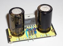
Nice board Peter! I wonder how it sounds.
--
Brian
By the way, I got the first batch of components today, some Riken resistors and some Caddock resistors. I had to source the Caddocks from 5 different vendors to avoid the 5 week lead time on them directly from Caddock. At the rate going now, I will have to find more vendors.
--
Brian
By the way, I got the first batch of components today, some Riken resistors and some Caddock resistors. I had to source the Caddocks from 5 different vendors to avoid the 5 week lead time on them directly from Caddock. At the rate going now, I will have to find more vendors.
Attachments

- Status
- Not open for further replies.
- Home
- Group Buys
- Group order of non-inverted LM3875 pc boards? Anyone interested?