Hi Paolo,Hello chanh
i stumbled in this thread because i'm finally about to build the unit for my QSXM2 riaa preamp (it's working fine on batteries).
D7 and D8 seem to be reversed in your photos.
Probably i'm blind or just i have to read deeper in the manual.
Cheers
Paolo
Really appreciated your observations/input! I am virtually giving up on this being non-electronic background. 🙁
You are right! D7/8 were definitely reversed for the intended conversion negative voltage to positive one. Have I done this wrong? By default, it is otherway around but default is for negative voltage outputting.
Cheers again, Paolo!
Chanh
If you compare, where do you start to have a difference between the halves? If you have the parts exactly as the real positive side it will work. Have you fixed the supply voltage of the opamp? It seem not in the pictures, besides if you have applied the reversed voltage it may be broken.
Last edited:
Hi P-A,
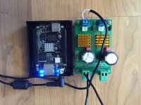
I did swap the legs at OpAmp.
Pls see photos;
Chanh
I did swap the legs at OpAmp.
Pls see photos;
An externally hosted image should be here but it was not working when we last tested it.
An externally hosted image should be here but it was not working when we last tested it.
An externally hosted image should be here but it was not working when we last tested it.
An externally hosted image should be here but it was not working when we last tested it.
Chanh
Can you measure the voltage on the IN pin of the LM317, pin 2, 3, 4, 6 and 7 on the opamp?
Measure the OUT pin of the LM317.
Measure the OUT pin of the LM317.
Hi P-A,Can you measure the voltage on the IN pin of the LM317, pin 2, 3, 4, 6 and 7 on the opamp?
Measure the OUT pin of the LM317.
I took measurements as follows;
LM317
Voltage in = 16.05VDC
Voltage out = 5.73VDC
Voltage adj = 4.49VDC
OPAmp AD825
1 = 0VDC
2 = 1.50VDC
3= 0.97VDC
4= 0VDC
5= 0VDC
6= 1.13VDC
7= 5.37VDC
8= 0VDC
The voltage reference seems not OK. Make sure that you'll get 2.5 V from it. The reference voltage is lower than the feedback (pin 2) so therefor the opamp is locked to min value. Have you swapped A and K and made adjustments for getting 2.5 V?
Here is to confirm that Diyinhk 5V ps works with BBB.I have damaged one BBB via Doede's 5V PS. Have got the Diyinhk version here too, I will try tomorrow and advise. Definitely this SSR03 will not work.
Attachments
The voltages from LM317 on negative rail were slightly off from the truth positive side. I have reserved leg 7 and 4 on the OpAmp as shown on the photo previously.The voltage reference seems not OK. Make sure that you'll get 2.5 V from it. The reference voltage is lower than the feedback (pin 2) so therefor the opamp is locked to min value. Have you swapped A and K and made adjustments for getting 2.5 V?
What are A and K that needed a swap and how do I made adjustment for getting 2.5V?
Chanh
I mean the LM431. Compare the schematics in this section. Check were anode and cathode goes. The positive side is working and has a 2.5 V reference voltage.
Yes, LM431 was also swapped, Pin2 and Pin3 was interchanged. I measured both pin2/3, none was reading at 2.5V.
What is the voltage across the cathode and reference? How much current have you the throughout the LM431, R38
R44, R46, values? Have you compared the halves REALLY carefully?
R44, R46, values? Have you compared the halves REALLY carefully?
I 've just finished two SSR03 var. 12V (431). DC is pretty stable but +/- 11.88V (with no load) only. What should I do? Is there something wrong possible?
Thanks
Thanks
DC is pretty stable but +/- 11.88V (with no load) only
That amounts to exactly 1% deviation from the target... I guess whatever you want to power with it won't mind.
1% error untrimmed with a 2% reference plus 4 % resistor tolerance is pretty good but you can of course trim the voltage but it has no practical relevance.
Expected value is 6%!
Expected value is 6%!
... it has no practical relevance...
Yes it's true and I guess the stability is more important than 1% reduced voltage.. thanks for your responses 😉
Last edited:
BOM/documents
Hi. Sorry for being so dense, but I don't seem to be able to find the documentation for the board. I got four boards and finally had time to start one but the wiki link to downloading the file doesn't work for me and the Sojostrom website takes me to a donate first page. I know it's simple, bu I can't figure out how to get the file(s)...😱
Hi. Sorry for being so dense, but I don't seem to be able to find the documentation for the board. I got four boards and finally had time to start one but the wiki link to downloading the file doesn't work for me and the Sojostrom website takes me to a donate first page. I know it's simple, bu I can't figure out how to get the file(s)...😱
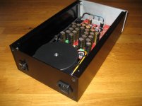
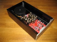
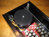
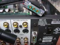
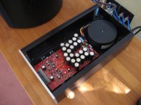
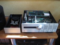
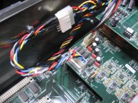
Finished +/-15V Supply as replacement for SMPS in Lexicon MC-12
Hello,
just finished the SSR03 as a substitute for the +/-15V SMPS in a Lexicon MC-12/JBL SDP-40 and it works fantastic!🙂
The Lex needs about 900mA for the +15V rail for analog supply, so cooling on bottom plate is an easy and good solution.
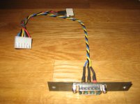
The free slot on the back of the MC-12 is used to feed in the external power with D-SUB power connectors. All internal MC12 wiring is realised with plugs (no soldering) and is reversible.
The aluminium enclosure is chinese made bought on Aliedexpress for $120 incl. shipment.
The sound quality is much more better compared with the switch-mode-supply used by Lexicon.
The SSR03 is a great product!
Hello,
just finished the SSR03 as a substitute for the +/-15V SMPS in a Lexicon MC-12/JBL SDP-40 and it works fantastic!🙂
The Lex needs about 900mA for the +15V rail for analog supply, so cooling on bottom plate is an easy and good solution.
The free slot on the back of the MC-12 is used to feed in the external power with D-SUB power connectors. All internal MC12 wiring is realised with plugs (no soldering) and is reversible.
The aluminium enclosure is chinese made bought on Aliedexpress for $120 incl. shipment.
The sound quality is much more better compared with the switch-mode-supply used by Lexicon.
The SSR03 is a great product!
Attachments


- Home
- Group Buys
- Group Buy: SSR03 Super Regulator Power Supply