Another newbie question: any problem using the T-reg in a parallel feed amp?
I ask b/c I've read that some regulators do not get along with capacitive loads.
In my case, the output tubes are choke-loaded, with a 10 uF parafeed cap from anode to the primary of the output transformer. I'm not sure if the parafeed cap qualifies as a capacitive load on turn on, and if it does, whether it is a problem.
MTIA, Derek
Derek, all regulators have capacitors at their output, so they are intrinsically capacitively loaded. That cap has an important function for stability.
At any rate, capacitive loads on circuits are only of interest if there is an actual AC signal that is capacitively loaded. The cap load then causes a phase shift between the AC signal voltage, for instance the output of an amp, and the load current. It is that phase shift that can sometimes cause problems.
With a regulator, there is no AC signal that can be phase shifted with the load current; the reg output is DC. So the term cap load in the context of phase shift has no meaning for a regulator.*
I would be very interested where you have read that is ws an issue.
Jan
*As noted, a minimum cap load, with a non-zero ESR, is needed for stability. There is internally in the reg a phase shift but beyond the min capacity, further cap load has no effect.
Many thanks again, Jan.
My concern about capacitive loads was piqued after reading a brief exchange between forum members tomchr and tubelab about short-circuit/fault testing a high voltage regulator (posts 21 and 24): 21st Century Maida Regulator - Page 3 - diyAudio
That sent me down a rabbit hole of interweb reading, from which I gleaned that a specific capacitive load is deliberately built into the output of a voltage regulator for stability. Which got me wondering whether an additional external capacitive load might destabilize a regulator that was designed to perform only into its built-in capacitance. And at that point I was well over my head and figured that I just better ask.
cheers and thanks, Derek
T-Reg feeding 2 tube stages
I want to feed 2 or 3 tubestages via the T-Reg. As each stage needs a different voltage, what would be the best way to do this?
Drop the voltage by a RC combo or does this have negative impact on the T-Reg performance?
Best
René
I want to feed 2 or 3 tubestages via the T-Reg. As each stage needs a different voltage, what would be the best way to do this?
Drop the voltage by a RC combo or does this have negative impact on the T-Reg performance?
Best
René
Yes, whatever you do after the T-reg will compromise its performance.
In your case, I would use the T-reg for the most sensitive stage, probably the first stage which probably needs the lowest voltage, and feed the less critical stages with a (higher) voltage taken from before the T-reg.
Jan
In your case, I would use the T-reg for the most sensitive stage, probably the first stage which probably needs the lowest voltage, and feed the less critical stages with a (higher) voltage taken from before the T-reg.
Jan
I have no plans for a negative high voltage regulator. But of course you can use the T-reg high voltage regulator to provide a negative high voltage, by using a separate transformer winding. You can then ground the T-reg output and use the T-reg 'ground' as the negative output. That gives you exactly the same performance in a negative voltage.
I'll put an example up on the website today or tomorrow.
Jan
I'll put an example up on the website today or tomorrow.
Jan
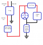
Looking for some help troubleshooting my installation of the T-Reg in a parallel feed 300B SET amp. The driver tubes already have their own plate voltage regulators, so I want to use the T-reg to regulate the B+ feeding the 300B output tubes to eliminate line voltage variation. Block diagram of my installation is attached.
With 470 very well filtered VDC feeding the T-reg, I trimmed the output voltage of the reg to 450 VDC using the on-board trimmer pot. But the 450 VDC wasn't stable. It continuously bounced around +/- 0,5 V (approx. 1V pk-pk) - I assume in keeping with my mains voltage variations.
Maximum current draw of both output stages (left and right channels) is 160 mA, and I have the T-reg max current set to 200 mA using 3R and 1R resistors.
Based on the above and attached info, does anyone see an obvious cause of my problem? Happy to provide any other info required.
Many thanks in advance, Derek
Attachments
Last edited:
Deke, that output should definitely NOT bounce around, it should be rock stable, whatever the mains voltage (assuming the mains doesn't drop so far that the input to the T-reg gets below the set output value).
I think your current limit is a bit tight, there is some tolerance there depending on the transistors used. Try to set it higher like to 250 or 300mA, it is only meant to get activated in case of a problem, not to exactly limit the circuit.
Don't forget that the 160mA is a DC value (I assume) and in use the anode current will vary and get above (and below) 160mA.
Normally there is a power supply capacitor at the load, which is not in your diagram. Is it there?
I am not familiar with such a circuit, the plate choke is the load I guess, and in that case you definitely should have a largish cap at the T-reg output.
Jan
Last edited:
Many thanks Jan for the quick response.
Great. I will increase the current limit as you suggest.
The T-reg is fed by a CLCLC filter, but there is no additional load capacitor after the T-reg. The T-reg directly feeds the plate choke.
So a 600+ VDC rated capacitor across +ve and -ve outputs of the T-reg? Do you have a guesstimate of the range of appropriate capacitance values? I expect I may have to play around with different values, but a ballpark starting point would be most helpful.
Alternatively, do you think I could insert the T-reg between the L and the C of the final LC stage of the CLCLC filter? The last cap of the power supply is pretty big: a 1500 uF film capacitor.
cheers and many thanks, Derek
I think your current limit is a bit tight, there is some tolerance there depending on the transistors used. Try to set it higher like to 250 or 300mA ...
Great. I will increase the current limit as you suggest.
Normally there is a power supply capacitor at the load, which is not in your diagram. Is it there?
The T-reg is fed by a CLCLC filter, but there is no additional load capacitor after the T-reg. The T-reg directly feeds the plate choke.
I am not familiar with such a circuit, the plate choke is the load I guess, and in that case you definitely should have a largish cap at the T-reg output.
So a 600+ VDC rated capacitor across +ve and -ve outputs of the T-reg? Do you have a guesstimate of the range of appropriate capacitance values? I expect I may have to play around with different values, but a ballpark starting point would be most helpful.
Alternatively, do you think I could insert the T-reg between the L and the C of the final LC stage of the CLCLC filter? The last cap of the power supply is pretty big: a 1500 uF film capacitor.
cheers and many thanks, Derek
It is just that I don't know how a voltage regulator reacts to a high L load.
Leave all the C-L stuff (except the anode load) at the input side.
Try 10uF at the T-reg output, but first check how it goes with higher current limit please. I am curious ;-)
jan
Leave all the C-L stuff (except the anode load) at the input side.
Try 10uF at the T-reg output, but first check how it goes with higher current limit please. I am curious ;-)
jan
Thanks Jan. Will do. I will first try current shut off set to 300 mA. If that doesn't do it, I will add a 10 uF film cap across the output. i will try this this evening and report back.
cheers and many thanks, Derek
cheers and many thanks, Derek
- Home
- Group Buys
- Group Buy for Jan's high voltage regulator