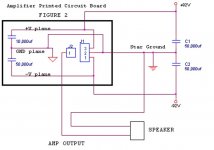
Figure 2 is a block diagram of
an amplifier printed circuit board
with 10,000uf of capacitance per rail
mounted on the circuit board.
The board has a dedicated
inner layer ground and power
plane for power distribution.
Power comes in via a connector
J1 and the amplifier output is J2
connector.
If I ground all the active circuits
including the 10,000 uf capacitors
to the ground plane on the board,
will this work good or will the
charging/disharging of the 10,000uf
capacitors cause too much noise
for the active circuits?
Or
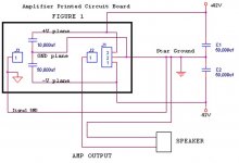
see figure 1 for plan b
..... second post.....
an amplifier printed circuit board
with 10,000uf of capacitance per rail
mounted on the circuit board.
The board has a dedicated
inner layer ground and power
plane for power distribution.
Power comes in via a connector
J1 and the amplifier output is J2
connector.
If I ground all the active circuits
including the 10,000 uf capacitors
to the ground plane on the board,
will this work good or will the
charging/disharging of the 10,000uf
capacitors cause too much noise
for the active circuits?
Or
see figure 1 for plan b
..... second post.....
Attachments
I dont think its an issue that you have 2 wires returning to the main voltage rail ground......there is is one thing that I have noticed in all the designs I have seen in the forums here...I have always placed a bleeder resistor off the main p/s caps...maybe I`m wrong from doing that
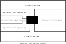
This is what I'm thinking for the
ground plane on the circuit board.
The main input gnd connector is the black box and the black lines represents
the insolation on the plane to create
the mixed gnd planes to form a star
ground on the pcb.
The large current will flow to the
+V and -V power capacitors,
this should isolate the sensitive
active circuits from noise ?
The input gnd connector wires
will be connected to the external power
supply reservoir (not shown).
Is this ok?
Attachments
- Status
- Not open for further replies.