Not sure whether this is the best section for this topic.
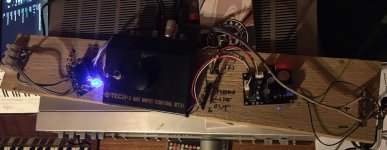
I've put together a simple "integrated" amp for listening to my turntable using an off the shelf Class D board and phono preamp (see links and poor quality photo below). These are both powered from the same 19v laptop supply. I have butchered an input selector switch unit to give RCA inputs and allow other (line) inputs. I have also added a volume pot.
Currently it's not mounted in a proper case, but boards are screwed to a plank of wood, and it's all working absolutely fine with (almost) all grounds connected and no shielding of signal wires. For now I've been connecting the turntable ground wire to the RCA plug grounds which has been effective in cancelling any hum. There's a labelled ground point on the phono preamp board which I've not needed to connect.
I'm happy enough with the performance of this that I've decided to mount it on a proper metal chassis. It sounds better than it has any right to driving some quite decent (and large) speakers. Not high end but definitely HiFi.
I'm trying to plan how best to lay it out and wondering how to approach grounding. I'm not overly worried about obvious unwanted hum as it works fine as is, but I'd like to follow best practice so that it works as well as it can.
Below are all the grounding points:
I'm thinking of 3 basic approaches:
1. Connect all signal grounds and power grounds logically to each other. Ground the TT and PSU and RCA sockets to the case. This is roughly the current scheme, and it works. I could potentially use shielded wiring internally with this approach.
2. Only connect positive signal and power wiring, connect grounds to casework at nearest point
3. Only connect positive signal and power wiring, connect grounds to casework at common point (star) in this case I'd probably keep RCA socket grounds insulated from the case and use a bar (solid copper wire) to tie their grounds together.
It's very possible I'm missing something obvious here. Hope it all makes sense. I realise it's quite a basic project but the aim is to do it right - and squeeze as much performance as possible out of these basic components.
I’d welcome any thoughts or suggestions on what’s likely to be the best way to hook it all up.
https://www.ebay.co.uk/itm/265099568381
https://www.ebay.co.uk/itm/186733669961
I've put together a simple "integrated" amp for listening to my turntable using an off the shelf Class D board and phono preamp (see links and poor quality photo below). These are both powered from the same 19v laptop supply. I have butchered an input selector switch unit to give RCA inputs and allow other (line) inputs. I have also added a volume pot.
Currently it's not mounted in a proper case, but boards are screwed to a plank of wood, and it's all working absolutely fine with (almost) all grounds connected and no shielding of signal wires. For now I've been connecting the turntable ground wire to the RCA plug grounds which has been effective in cancelling any hum. There's a labelled ground point on the phono preamp board which I've not needed to connect.
I'm happy enough with the performance of this that I've decided to mount it on a proper metal chassis. It sounds better than it has any right to driving some quite decent (and large) speakers. Not high end but definitely HiFi.
I'm trying to plan how best to lay it out and wondering how to approach grounding. I'm not overly worried about obvious unwanted hum as it works fine as is, but I'd like to follow best practice so that it works as well as it can.
Below are all the grounding points:
- signal and power grounds on 2 circuit boards, plus the turntable ground on the preamp board.
- PSU -ve
- RCA socket grounds
- Potentiometer ground
- the (aluminium) case, and I would assume I would connect the binding post for turntable ground directly to this.
I'm thinking of 3 basic approaches:
1. Connect all signal grounds and power grounds logically to each other. Ground the TT and PSU and RCA sockets to the case. This is roughly the current scheme, and it works. I could potentially use shielded wiring internally with this approach.
2. Only connect positive signal and power wiring, connect grounds to casework at nearest point
3. Only connect positive signal and power wiring, connect grounds to casework at common point (star) in this case I'd probably keep RCA socket grounds insulated from the case and use a bar (solid copper wire) to tie their grounds together.
It's very possible I'm missing something obvious here. Hope it all makes sense. I realise it's quite a basic project but the aim is to do it right - and squeeze as much performance as possible out of these basic components.
I’d welcome any thoughts or suggestions on what’s likely to be the best way to hook it all up.
https://www.ebay.co.uk/itm/265099568381
https://www.ebay.co.uk/itm/186733669961
Attachments
Last edited: